Shaft-misalignment-measuring device, a shaft-misalignment-measuring method, a single-shaft combined plant using the shaft-misalignment-measuring device and a start-up method of the single-shaft combined plant

a technology of shaft alignment and measuring device, which is applied in the direction of engine starters, turbine/propulsion engine ignition, instruments, etc., can solve the problem that the steam to be supplied to the steam turbine cannot be generated by a heat recovery steam generator

Active Publication Date: 2007-02-13
MITSUBISHI HITACHIPOWER SYST LTD
View PDF21 Cites 26 Cited by
  • Summary
  • Abstract
  • Description
  • Claims
  • Application Information

AI Technical Summary

Benefits of technology

[0013]It is an object of the present invention to provide a shaft-misalignment-measuring device which measures misalignment between two shafts when a clutch is engaged; and a single-shaft combined plant which is eqipped with this shaft-misalignment-measuring device. It is another object of the present invention to provide a start-up method of a single-shaft combined plant which changes over start-up action based on the misalignment between the center position of the steam-turbine shaft and the center position of the gas-turbine shaft at the start-up time.

Problems solved by technology

However, steam to be supplied to the steam turbine cannot be generated by a heat recovery steam generator which generates steam by using the exhaust gas of a gas turbine until the electrical output of a generator rotated by a gas turbine is increased.
Further, in a conventional single-shaft combined plant, it is necessary to place a gas turbine, a steam turbine and a generator in a line and an axial-flow exhaust type of steam turbine cannot be applied.

Method used


Image

  • Shaft-misalignment-measuring device, a shaft-misalignment-measuring method, a single-shaft combined plant using the shaft-misalignment-measuring device and a start-up method of the single-shaft combined plant
  • Shaft-misalignment-measuring device, a shaft-misalignment-measuring method, a single-shaft combined plant using the shaft-misalignment-measuring device and a start-up method of the single-shaft combined plant
  • Shaft-misalignment-measuring device, a shaft-misalignment-measuring method, a single-shaft combined plant using the shaft-misalignment-measuring device and a start-up method of the single-shaft combined plant

Examples


Embodiment Construction

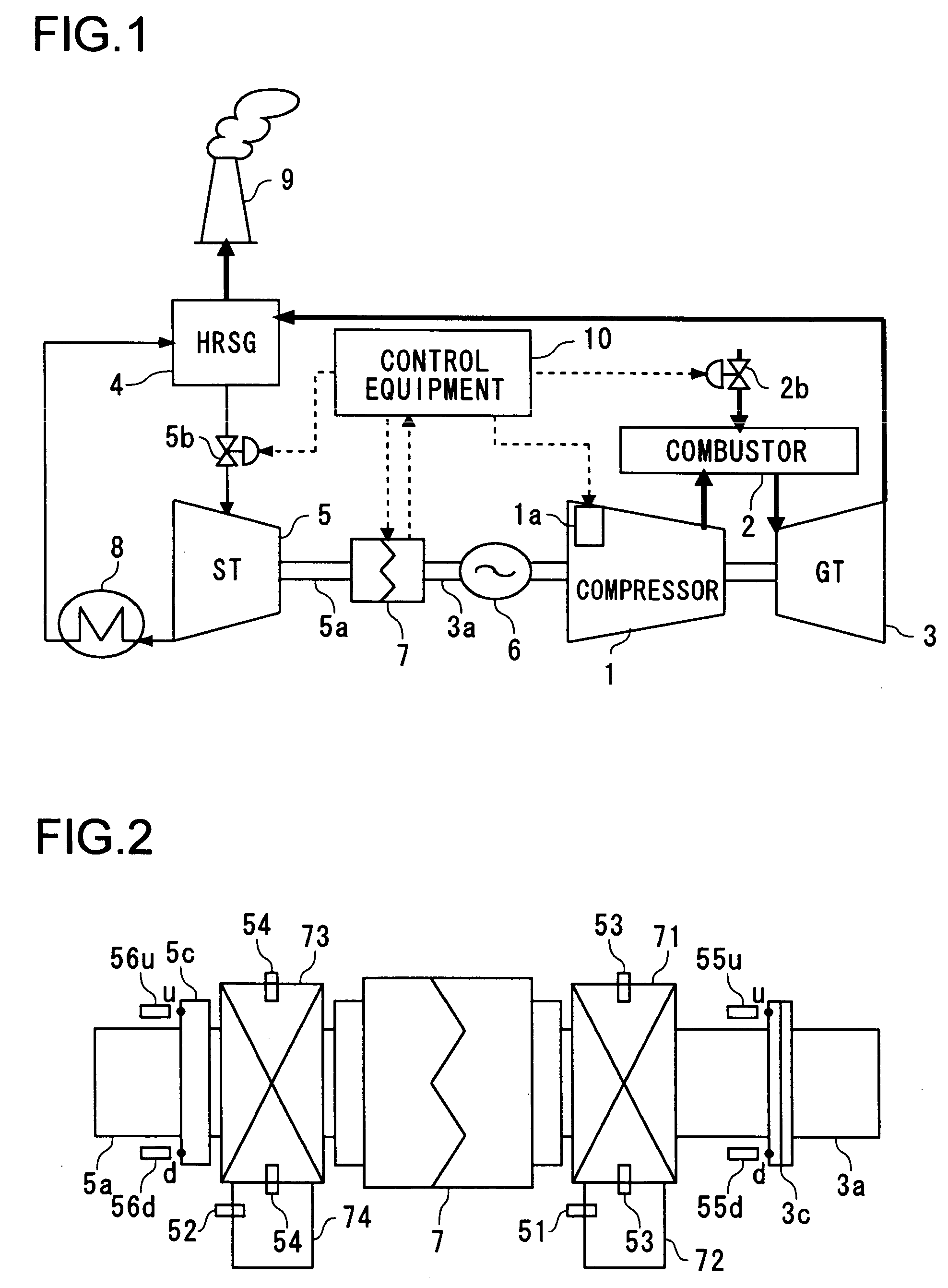
[0041]Referring now to the drawings, an embodiment of the present invention will be described hereinafter. FIG. 1 is a block diagram showing the construction of a single-shaft combined plant.

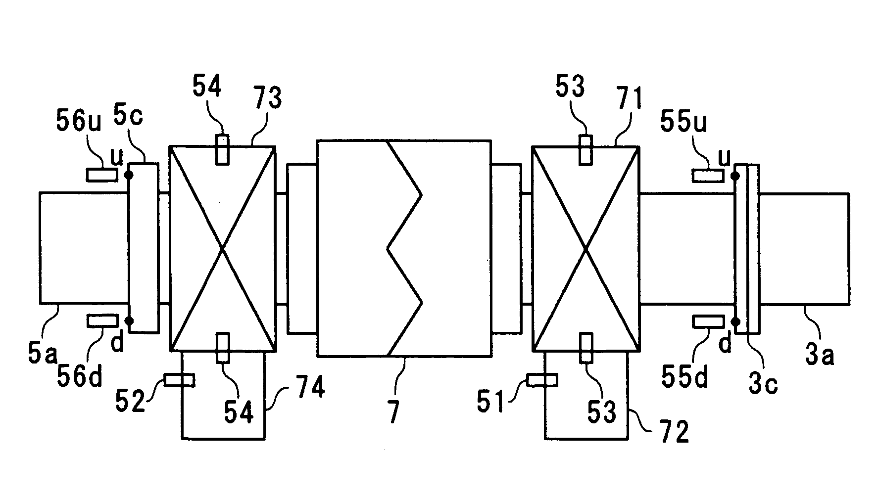
[0042]A single-shaft combined plant in FIG. 1 consists of a compressor 1 which compresses the ambient air; a combustor 2 which burns fuel with compressed air from the compressor 1 to supply combustion gas; a gas turbine 3 which is rotated with combustion gas being supplied from the combustor 2: an heat recovery steam generator (HRSG) 4 which generates steam with exhaust gas from the gas turbine 3; a steam turbine 5 which is rotated with steam from the HRSG 4; a generator 6 which is rotated by the gas turbine 3 and the steam turbine 5; a clutch 7 which connects and disconnects a gas-turbine shaft 3a and a steam-turbine shaft 5a; a condenser 8 which recovers steam exhausted from the steam turbine 5 and supplies the recovered steam to the HRSG 4; a chimney 9 which emits exhaust gas from the gas tur...


PUM

PropertyMeasurementUnit
angleaaaaaaaaaa
temperatureaaaaaaaaaa
temperaturesaaaaaaaaaa

Abstract

In a control equipment 10, shaft-misalignment amount of a shaft 3a of a gas turbine 3 and a shaft 5a of a steam turbine 5 is measured and speed-increase ratio of rotation speed and heat soak time of the steam turbine 5 are set in accordance with the measured shaft-misalignment amount so as to have the shaft-misalignment amount stay within a permissible range when a clutch 7 connects the shafts 3a and 5a.

Description

BACKGROUND OF THE INVENTION[0001]1. Field of the Invention[0002]The present invention is based on the Japanese Patent Application No. 2003-343442 applied on Oct. 1, 2003.[0003]The present invention relates to a shaft-misalignment-measuring device which measures the misalignment of two shafts having a clutch engaged thereto; a shaft-misalignment-measuring method; a single-shaft combined plant employing the shaft-misalignment-measuring device; and a start-up method of the single-shaft combined plant.[0004]2. Description of the Prior Art[0005]In recent years, a single-shaft combined plant having a gas turbine connected directly to a steam turbine with one shaft serves as a combined plant of high efficiency which can flexibly respond to a change of electrical consumption amount per day, emitting a little amount of toxic substances such as NOx. Conventionally, a single-shaft combined plant constructed in the above-mentioned manner actuates a gas turbine and a steam turbine simultaneously...

Claims


Application Information

Patent Timeline
Patent Type & Authority Patents(United States)
IPC IPC(8): G01N25/00G01B13/19G01B21/00F01D19/00F01D25/00F01K13/02F01K23/10F01K23/14F01K23/16F02C6/00F02C6/18F02C7/057F02C7/06F02C7/26F02C9/48G01N25/16
CPCG01N25/16Y02E20/16
Inventor TANAKA, SATOSHISHIMADA, MASAMITSUTAKEDA, KENYUKITAGAWA, RYUTAROINOUE, FUMIKATSU
Owner MITSUBISHI HITACHIPOWER SYST LTD
Why Eureka
Try Eureka