Rotary connector

a technology of rotary connectors and connectors, applied in the direction of current collectors, electrical devices, rotary current collectors, etc., can solve the problems of sliding portions of the top plate, control walls, and /i>generating unusual noise, and achieve the effect of inhibiting the noise generated by sliding portions

Active Publication Date: 2007-02-13
ALPS ALPINE CO LTD
View PDF6 Cites 16 Cited by
  • Summary
  • Abstract
  • Description
  • Claims
  • Application Information

AI Technical Summary

Benefits of technology

[0010]In light of the above circumstances of the related art, an object of the present invention is to provide a rotary connector capable of inhibiting unusual noise generated from sliding portions.
[0012]In the rotary connector having the above structure, the edge around the central hole of the bottom plate, which is a component of the stator housing, is held between the spacer fixed to the outer circumferential surface of the bottom part of the inner cylindrical portion of the upper rotor and the flange of the lower rotor fixed to the inner circumferential surface of the inner cylindrical portion. Based on the holding portions, therefore, the integrated upper and lower rotors may be held in the axial direction with respect to the stator housing. Thus sliding surfaces serving as the base of the product may be positioned near the center of rotation, and accordingly they may be more readily maintained at high dimensional accuracy. This allows for the inhibition of the unusual noise generated from the sliding surfaces.
[0013]In the above structure, the spacer and the lower rotor are preferably made of a synthetic resin different from that for the bottom plate. This allows for a more effective reduction of the unusual noise generated from the sliding surfaces.

Problems solved by technology

As a result, unfortunately, the sliding portions of the top plate 27a and the control wall 25a generate unusual noise when the rotor housing 21 is rotated.

Method used


Image

  • Rotary connector
  • Rotary connector
  • Rotary connector

Examples


Embodiment Construction

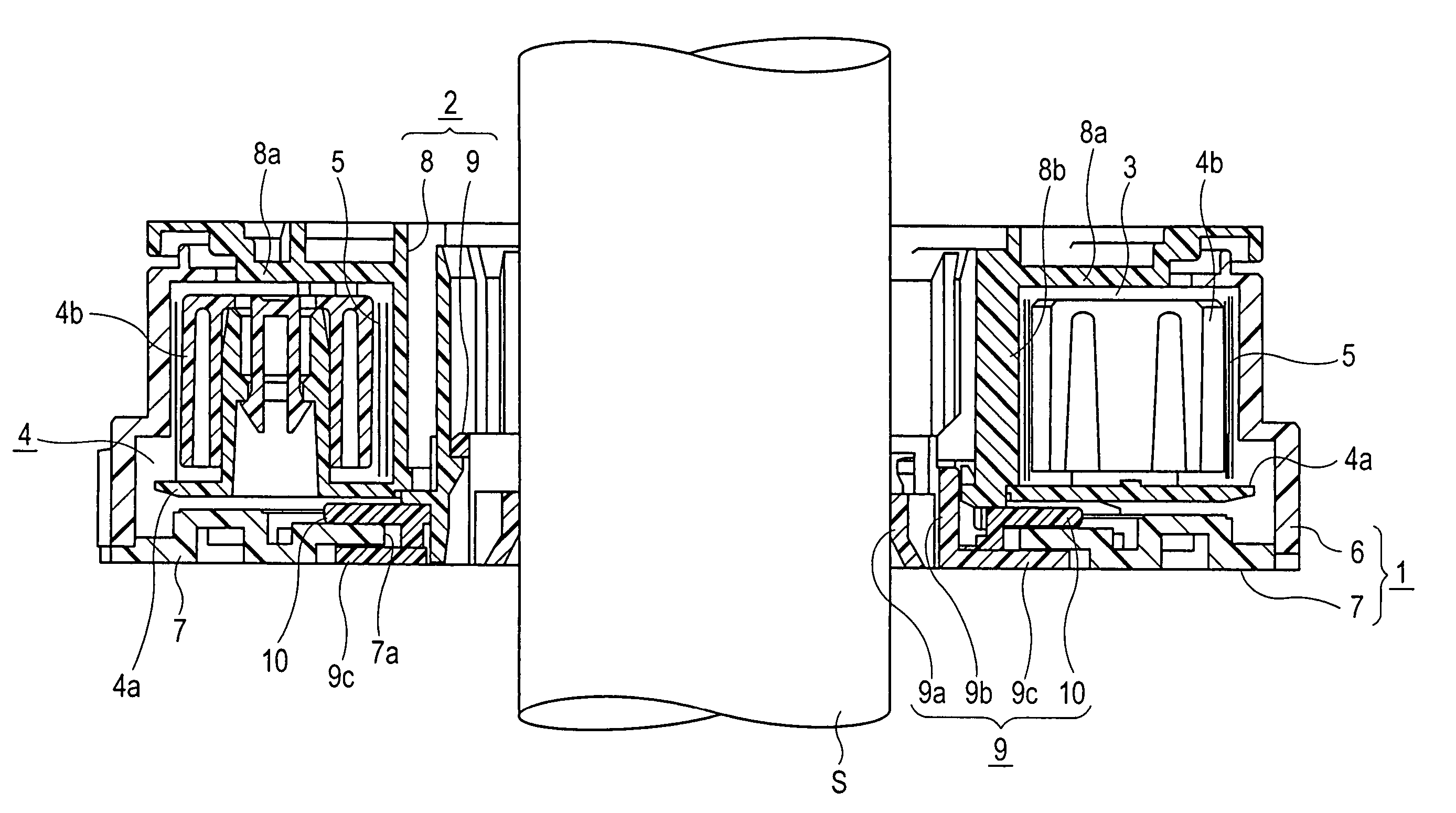
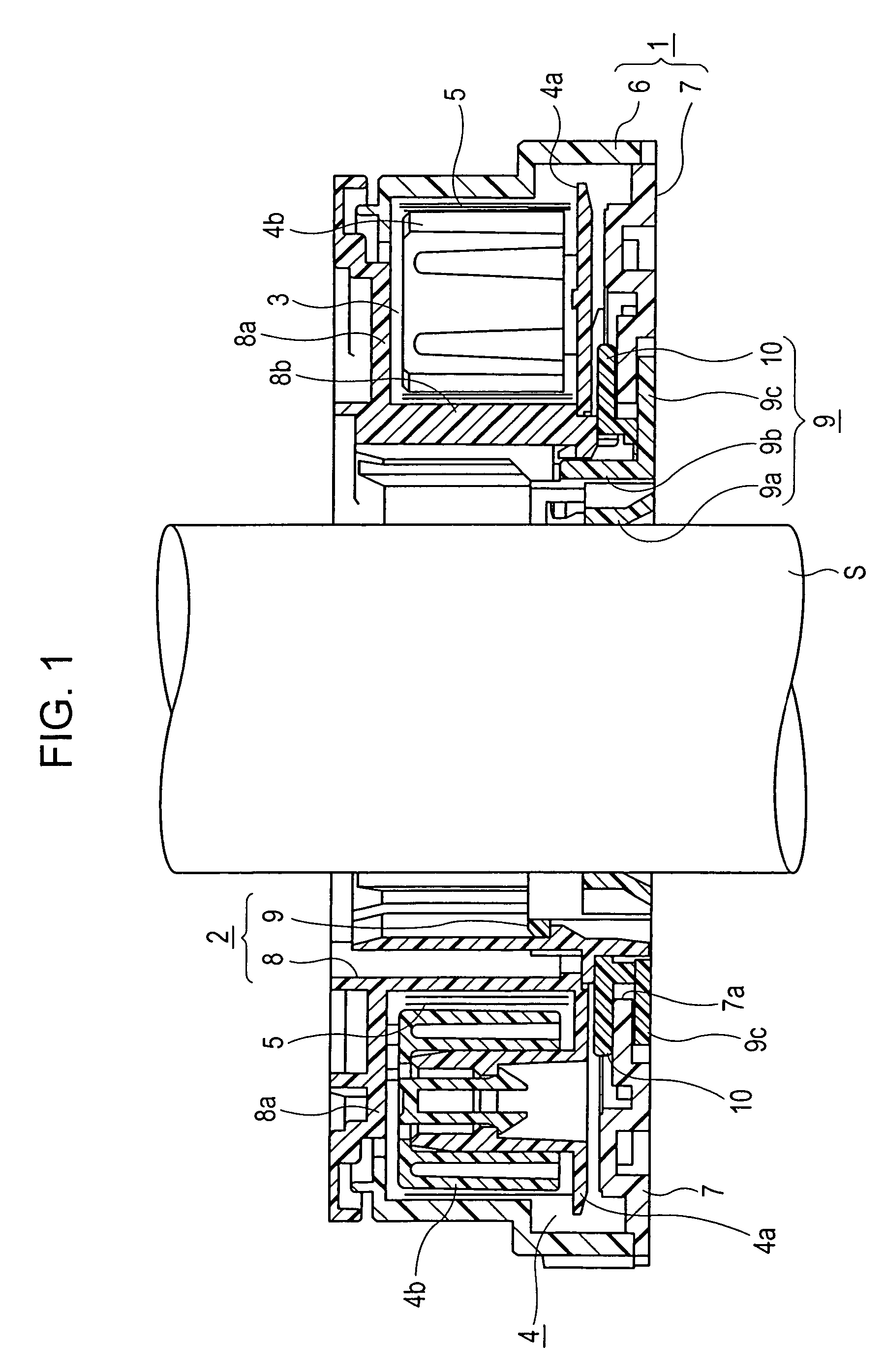
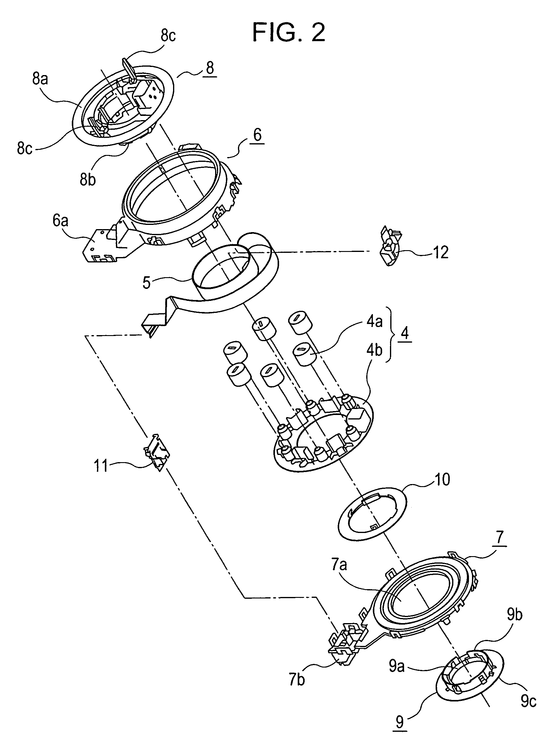
[0018]An embodiment of the present invention will now be described with reference to the drawings. FIG. 1 is a sectional view of a rotary connector, attached to a steering shaft, according to the embodiment of the present invention. FIG. 2 is an exploded perspective view of the rotary connector.

[0019]The rotary connector according to this embodiment mainly includes a stator housing 1, a rotor housing 2 rotatably attached to the stator housing 1, a holder 4 rotatably disposed in an annular accommodation space 3 defined between the housings 1 and 2, and a strip-like flat cable 5 wound and accommodated in the accommodation space 3.

[0020]The stator housing 1 includes an outer cylindrical portion 6 made of a synthetic resin, namely polyacetal (POM), and a bottom cover 7 made of another synthetic resin, namely polybutylene terephthalate (PBT). The outer cylindrical portion 6 and the bottom cover 7 are integrated with, for example, a snap fit. A lid 6a and attachment parts (not shown) are ...


PUM


Abstract

A rotary connector includes a stator housing including a bottom cover having a central hole and an outer cylindrical portion provided along the outer edge of the bottom cover; an upper rotor including an inner cylindrical portion and a top plate protruding outward from the top end thereof; a lower rotor inserted into the central hole and snap-fitted to the inner circumferential surface of the inner cylindrical portion; a holder rotatably disposed in an accommodation space defined between the upper rotor and the stator housing; a flat cable wounded and accommodated in the accommodation space with the winding direction thereof reversed at any point of the length; and a spacer fixed to the outer circumferential surface of the bottom part of the inner cylindrical portion. The spacer and the flange hold the edge of the bottom cover around the central hole.

Description

BACKGROUND OF THE INVENTION[0001]1. Field of the Invention[0002]The present invention relates to rotary connectors including a stator housing and a rotor housing that are rotatably coupled and electrically connected through a flexible cable, and particularly relates to a rotary connector including a rotor housing composed of upper and lower rotors coupled and integrated with, for example, a snap fit.[0003]2. Description of the Related Art[0004]Rotary connectors include, for example, a stator housing fixed to a combination switch assembly provided on a steering unit of an automobile, a rotor housing attached to a steering wheel, and a flexible cable wound in an annular accommodation space defined between the stator housing and the rotor housing. These rotary connectors are used to provide electrical connection for, for example, an airbag inflator provided on a steering wheel, which has a limited number of revolutions.[0005]Among such rotary connectors is a known rotary connector acco...

Claims


Application Information

Patent Timeline
Patent Type & Authority Patents(United States)
IPC IPC(8): H01R3/00
CPCH01R35/025
Inventor ARAKI, SHUNJICHIBA, SHU
Owner ALPS ALPINE CO LTD
Why Eureka
Try Eureka