Scroll compressor and refrigerating system

A scroll compressor and scroll technology, applied in the field of compressors, can solve problems such as noise

Pending Publication Date: 2020-03-27
ZHUHAI GREE REFRIGERATION TECH CENT OF ENERGY SAVING & ENVIRONMENTAL PROTECTION
View PDF0 Cites 1 Cited by
  • Summary
  • Abstract
  • Description
  • Claims
  • Application Information

AI Technical Summary

Problems solved by technology

[0004] The main purpose of the present invention is to provide a scroll compressor and refrigeration system to solve the problem that the scroll compressor in the prior art has noise during the injection compensation

Method used


Image

  • Scroll compressor and refrigerating system
  • Scroll compressor and refrigerating system
  • Scroll compressor and refrigerating system

Examples


Embodiment 1

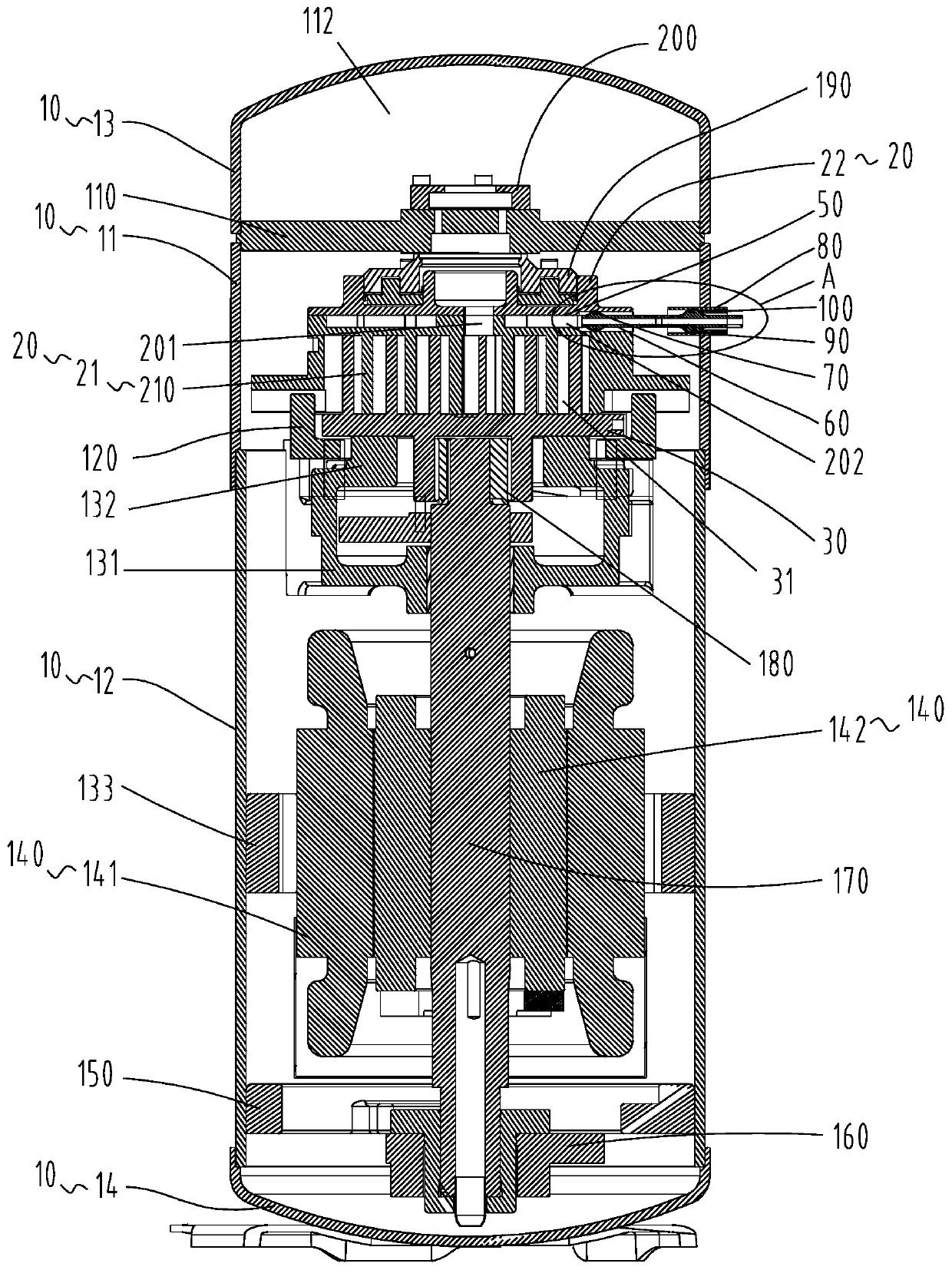
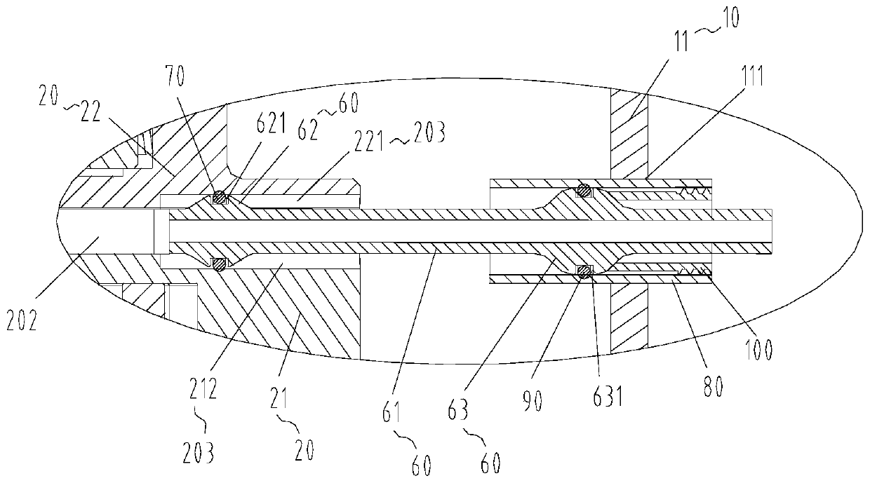
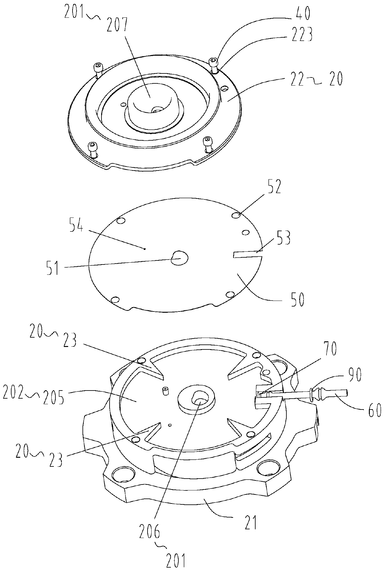
[0039] Such as Figure 1 to Figure 5 As shown, the scroll compressor includes a casing 10, a fixed scroll 20 and a movable scroll 30, the fixed scroll 20 is arranged in the casing 10, the movable scroll 30 is movably arranged in the fixed scroll 20, and the fixed scroll 20 A scroll cavity 31 is formed between the movable scroll 30; the fixed scroll 20 has an exhaust channel 201 for communicating with the scroll cavity 31, and the fixed scroll 20 has a muffler cavity 202 arranged around the periphery of the exhaust channel 201, The silencer chamber 202 and the exhaust passage 201 are arranged at intervals; wherein, the static scroll 20 is provided with an intake passage 203 communicating with the silencer chamber 202 , and the static scroll 20 is provided with a passageway connected with the silencer chamber 202 and the scroll chamber 31 Air intake hole 204 .

[0040] In this embodiment, the structure of the fixed scroll 20 is changed, thereby changing the circulation path of ...

Embodiment 2

[0070] The difference between the second embodiment and the first embodiment is only that the shape and size of the muffler cavity 202 are different. Such as Figure 6 As shown, the projection of the outer peripheral wall of the muffler cavity 202 on the radial section of the fixed scroll 20 includes a curved line segment and a third straight line segment 215, and the curved line segment includes a plurality of second circular arc line segments 213 connected in sequence, and each second circle The arc segments 213 protrude toward the side of the inner peripheral wall of the muffler chamber 202, and the two ends of the third straight segment 215 are respectively connected to the two ends of the curved segment; wherein, the intake passage 203 and the third straight segment 215 are located in the exhaust passage On the same side as 201 , the centerline of the intake passage 203 passes through the midpoint of the third straight line segment 215 . In this embodiment, through the a...

Embodiment 3

[0076] The difference between the third embodiment and the first embodiment is only that the shape and size of the muffler cavity 202 are different. Such as Figure 7 As shown, the projection of the outer peripheral wall of the muffler cavity 202 on the radial section of the fixed scroll 20 includes a third circular arc line segment 216 and a fourth straight line segment 217 opposite to each other, and a first curved line segment 218 and a second curved line segment 218 opposite to each other. Curved segment 219, the two ends of the first curved segment 218 are respectively connected with the first end of the third circular arc segment 216 and the first end of the fourth straight segment 217; the two ends of the second curved segment 219 are connected with the third circular arc respectively The second end of the line segment 216 is connected with the second end of the fourth straight segment 217; wherein, the intake passage 203 and the fourth straight segment 217 are located ...


PUM


Abstract

The invention provides a scroll compressor and a refrigerating system. The scroll compressor comprises a shell, a static vortex plate and a moving vortex plate. The static vortex plate is arranged inthe shell. The moving vortex plate is movably arranged in the static vortex plate. A vortex cavity is formed between the static vortex plate and the moving vortex plate. The static vortex plate is provided with an exhaust channel communicating with the vortex cavity. The static vortex plate is provided with a noise reduction cavity surrounding the periphery of the exhaust channel. The noise reduction cavity and the exhaust channel are arranged in a spaced manner. An air inlet channel communicating with the noise reduction cavity is arranged on the static vortex plate. An air inlet hole communicating with the noise reduction cavity and the vortex cavity is formed in the static vortex plate. By means of the technical scheme, the problem that noise exists during air injection compensation ofa scroll compressor in the prior art is solved.

Description

technical field [0001] The invention relates to the technical field of compressors, in particular to a scroll compressor and a refrigeration system. Background technique [0002] The scroll compressor has the advantages of simple structure, small size, light weight, high mechanical efficiency and stable operation. [0003] During the use of the scroll compressor, when the scroll compressor works under the condition of a large pressure ratio, it is necessary to use the air injection method to compensate the heating capacity. The gas injection structure in the related art directly injects gas into the vortex cavity, which will cause abnormal noise. Contents of the invention [0004] The main purpose of the present invention is to provide a scroll compressor and a refrigeration system to solve the problem of noise in the scroll compressor in the prior art during gas injection compensation. [0005] In order to achieve the above object, according to one aspect of the present...

Claims


Application Information

Patent Timeline
Patent Type & Authority Applications(China)
IPC IPC(8): F04C29/00F04C29/06F04C29/12F04C18/02
CPCF04C18/0215F04C29/00F04C29/065F04C29/068F04C29/12F04C2270/135
Inventor 曹贞文魏会军李立民郭求和刘虹志
Owner ZHUHAI GREE REFRIGERATION TECH CENT OF ENERGY SAVING & ENVIRONMENTAL PROTECTION
Why Eureka
Try Eureka