Method of manufacturing substrate for magnetic disk, apparatus for manufacturing substrate for magnetic disk, and method of manufacturing magnetic disk

a technology of magnetic disk and substrate, which is applied in the manufacture of base layers, grinding machine components, manufacturing tools, etc., can solve the problems of inability to obtain the proper flying height of the magnetic head, malfunction in reproduction, and contact with the magnetic head, so as to increase the information recording surface density of the magnetic disk, stable-quality disk substrate and magnetic disk, and low price and in large quantities

Inactive Publication Date: 2007-02-13
HOYA CORP
View PDF17 Cites 36 Cited by
  • Summary
  • Abstract
  • Description
  • Claims
  • Application Information

AI Technical Summary

Benefits of technology

[0016]In the use of mounting into the vehicle equipment or portable equipment, because of being carried or used in on-vehicle environment as different from the conventional use, cases of the hard disk drives (HDDs) are reduced in size and weight and the sizes (outer diameters) of magnetic disks are also reduced in diameter.
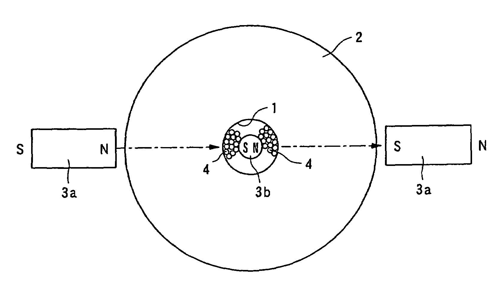
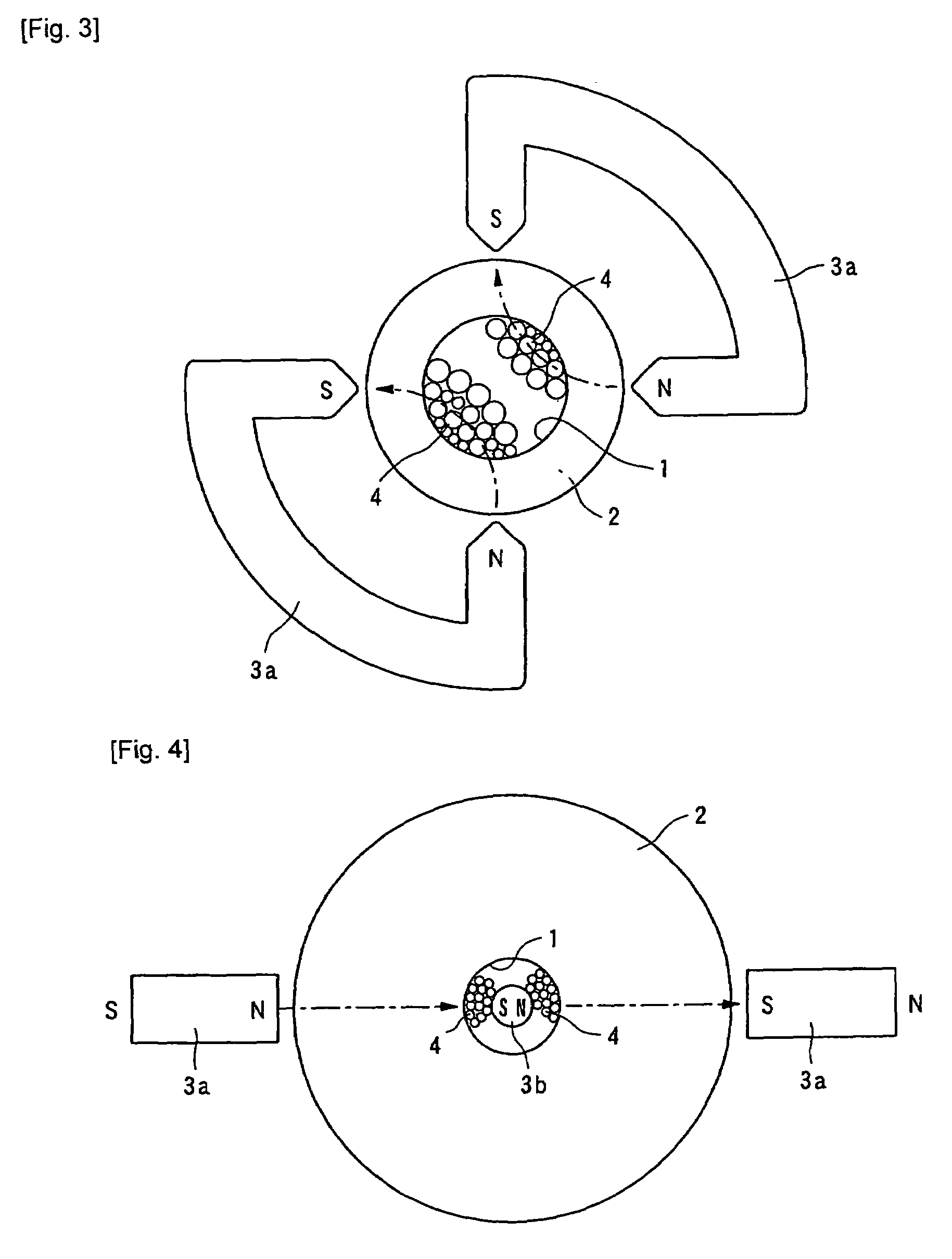
[0064]That is, this invention is, even if a circular hole at a center portion of a nonmagnetic disk substrate is reduced in diameter, capable of easily and satisfactorily polishing at least an end face on the inner peripheral side of the circular hole into a mirror surface, thereby enabling providing stable-quality disk substrates and magnetic disks at low prices and in large quantities, and of preventing the thermal asperity trouble and head crash with respect to a magnetic disk using the subject substrate for the magnetic disk, thereby serving to increase the information recording surface density in the magnetic disk.

Problems solved by technology

Since the magnetic disk is rotated at high speed during recording / reproduction, if the flying height of the magnetic head is reduced, there arises a greater possibility that the magnetic head contacts the surface of the magnetic disk so as to be crashed.
This is because if foreign matter is adhering to the surface of the disk substrate, it becomes a cause for a film defect of a magnetic thin film to be formed on the surface of the glass substrate or it becomes a cause for occurrence of a convex portion on the surface of the magnetic thin film so that a proper flying height of the magnetic head cannot be obtained.
In such a magnetoresistive head using the magnetoresistive effect element, when a small roughness is formed on the surface of a magnetic disk, a thermal asperity trouble may occur to cause malfunction in reproduction or the reproduction may be impossible.
This thermal asperity trouble is caused such that a convex portion formed on the surface of a magnetic disk due to foreign matter on a glass substrate generates adiabatic compression and adiabatic expansion of air in the vicinity of a magnetoresistive head due to high-speed rotation of the magnetic disk so that the magnetoresistive head generates heat to cause a change in resistance value of a magnetoresistive effect element and, therefore, electromagnetic conversion is adversely affected.
That is, such a thermal asperity trouble can be generated even in the case where the magnetic head does not contact the magnetic disk.
In this technique, although it is possible to prevent degradation of a strength of the glass substrate caused by the crack, the crack is broadened to form a hollow so that dust is easily captured instead and, therefore, the high cleaning of the surface of the disk substrate cannot be achieved.

Method used


Image

  • Method of manufacturing substrate for magnetic disk, apparatus for manufacturing substrate for magnetic disk, and method of manufacturing magnetic disk
  • Method of manufacturing substrate for magnetic disk, apparatus for manufacturing substrate for magnetic disk, and method of manufacturing magnetic disk
  • Method of manufacturing substrate for magnetic disk, apparatus for manufacturing substrate for magnetic disk, and method of manufacturing magnetic disk

Examples


example 1

[0158]Hereinbelow, examples of this invention will be described in detail.

[0159]In this example 1, substrates for magnetic disks were manufactured through the following processes.

[0160](1) Shaping Process, Lapping Process Molten aluminosilicate glass was formed into a disk shape by pressing to thereby obtain glass disks.

[0161]As the aluminosilicate glass, use was made of glass for chemical strengthening containing, as main components, 57 to 74 mol % of SiO2, 0 to 2.8 mol % of ZrO2, 3 to 15 mol % of Al2O3, 7 to 16 mol % of LiO2, and 4 to 14 mol % of Na2O.

[0162]Subsequently, lapping was applied to the main surfaces of the obtained glass disk substrates. In the lapping process, the lapping was carried out by the use of a double-side lapping machine and alumina abrasive particles to thereby achieve predetermined dimensional accuracy and shape accuracy of the glass substrates. Then, grinding was performed using a grindstone to thereby form a circular hole at a center portion of each glas...

example 2

[0179]In this example 2, magnetic disks were manufactured through the following processes.

[0180]On each of both main surfaces of each of the glass substrates for the magnetic disks obtained as described above, an Al—Ru alloy first underlayer, a Cr—Mo alloy second underlayer, a Co—Cr—Pt—B alloy magnetic layer, and a hydrogenated carbon protection layer were formed in turn by the use of a stationary opposing-type DC magnetron sputtering apparatus. Then, an alcohol-denatured perfluoropolyether lubricating layer was formed by the dip method. In this manner, the magnetic disks were obtained.

[0181]With respect to the obtained magnetic disks, it was confirmed that there was no occurrence of defect on the films such as the magnetic layers due to foreign matter. A glide test was performed and there was observed no hit (a head grazes a projection on the surface of a magnetic disk) or crash (a head collides with a projection on the surface of a magnetic disk). Further, a reproduction test was ...


PUM

PropertyMeasurementUnit
particle sizeaaaaaaaaaa
lengthaaaaaaaaaa
diameteraaaaaaaaaa

Abstract

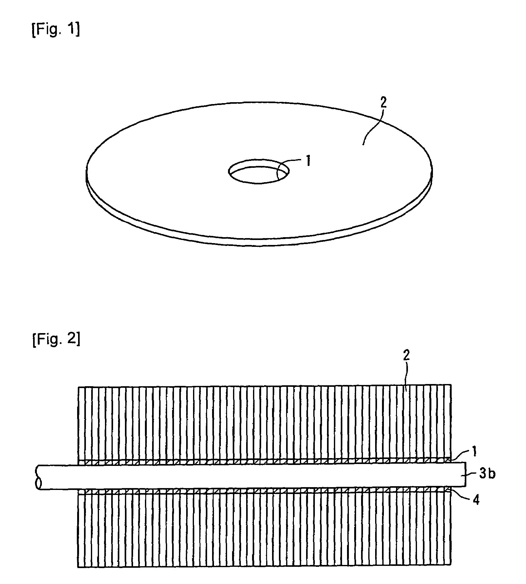
A magnetic polishing method capable of easily and satisfactorily polishing the inner peripheral end face of a circular hole (1) at the center part of a disk substrate (2) even if the diameter of the circular hole is reduced. By this method, a large quantity of disk substrates with stable quality can be supplied, thermal asperity trouble and head crush can be prevented from occurring on a magnetic disk, and the density of the information recording surface of the magnetic disk can be increased. In the method for polishing the inner peripheral end face of the circular hole (1) at the center part of the disk substrate (2), a magnetic field is formed on the inner peripheral side of the circular hole (1), abrasive materials (4) including magnetic particles and abrasive grains are held by the magnetic field in the circular hole, and the magnetic field is moved to the inner peripheral end face of the circular hole (1) to move the abrasive materials (4) to the inner peripheral end face of the circular hole (1) for polishing the inner peripheral end face of the circular hole (1).

Description

[0001]this application is a 371 of PCT / JP 04 / 09806 Jul. 9, 2004TECHNICAL FIELD [0002]This invention relates to a method and apparatus for manufacturing a substrate for a magnetic disk for use in a magnetic disk that serves as a recording medium in an information recording device such as a hard disk drive (HDD) and, in particular, relates to a method and apparatus for manufacturing a substrate for a magnetic disk which can suitably polish an inner peripheral end face and an outer peripheral end face of a substrate for a magnetic disk, or the like.BACKGROUND ART[0003]In recent years, various information processing devices have been proposed following the advancement of information society and further, information recording devices such as hard disk drives (HDDs) for use in those information processing devices has been proposed. In such information recording devices, larger information recording capacities and higher information recording densities have been required for the purpose of...

Claims


Application Information

Patent Timeline
Patent Type & Authority Patents(United States)
IPC IPC(8): B24B1/00G11B5/84
CPCG11B5/8404
Inventor UEDA, MASAAKIKASHIMA, RYUICHI
Owner HOYA CORP
Why Eureka
Try Eureka