Circuit breaker filter assembly

a circuit breaker and filter assembly technology, applied in the direction of air breakers, high-tension/heavy-dress switches, electrical apparatuses, etc., can solve the problems of short circuit between adjacent plates, high thermal, mechanical and electrical stresses of chambers and separable contacts,

Active Publication Date: 2007-02-13
SQUARE D CO
View PDF21 Cites 15 Cited by
  • Summary
  • Abstract
  • Description
  • Claims
  • Application Information

AI Technical Summary

Benefits of technology

[0013]In accordance with another aspect of the invention, a circuit breaker assembly comprises means for filtering a high energy arc comprising means for mounting at least two filter assemblies with a generally rectilinear filter housing having at least two filter mounting zones so as to define, in the aggregate, a filter assembly, means for sealingly engaging the filter body relative to the filter housing in response to forces encountered by the filter assembly both dining assembly and in operation, means for assembling a small hole diffuser having a peripheral configuration similar to the peripheral configuration of the filter bodies in the aggregate, when assembled, with the filter housing and interfitting within the filter housing, superimposed over the filter assemblies, means for interposing a spacer between the filters and the small hole diffuser, and means for engaging a molded coarse hole diffuser, defining a combined diffuser and spacer integrally molded as a single, one-piece unit, with the filter housing in close overlying engagement with the small hole diffuser, and means for diffusing the arc, comprising means for positioning and maintaining the arc stack and the filter assembly in assembled relation within the breaker housing, including maintaining compression on the gaskets and maintaining constant assembly force upon the assembly, equalizing compression loading of the gaskets and providing final positioning of the arc stack and filter assembly into the breaker case.

Problems solved by technology

Both the chamber and the separable contacts may be subject to high thermal, mechanical and electrical stresses.
Also, exposure of the arc plates or separators to heat and pressure from arc interruption can cause the plates to warp, causing a short circuit between adjacent plates, if touching.

Method used


Image

  • Circuit breaker filter assembly
  • Circuit breaker filter assembly
  • Circuit breaker filter assembly

Examples


Embodiment Construction

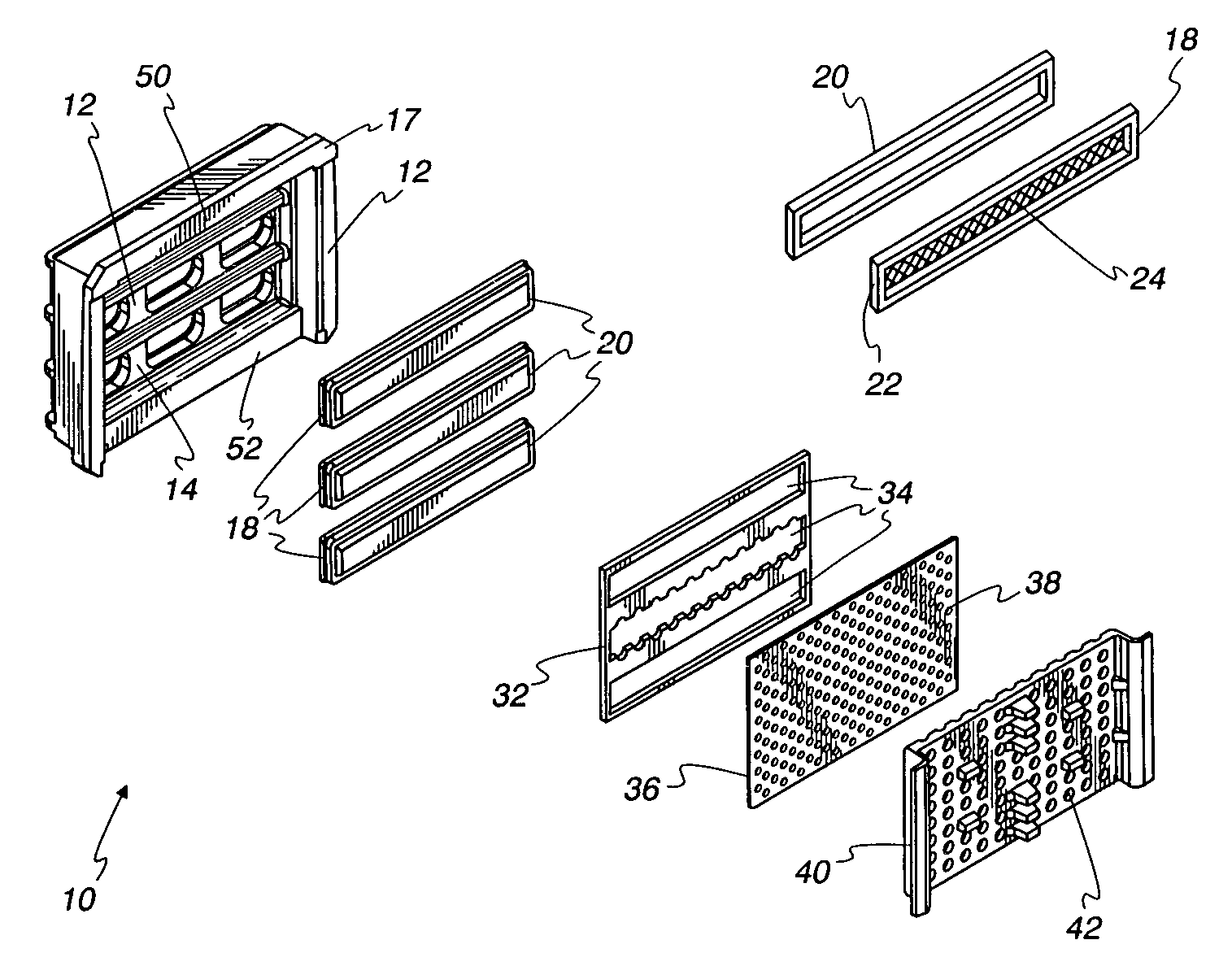
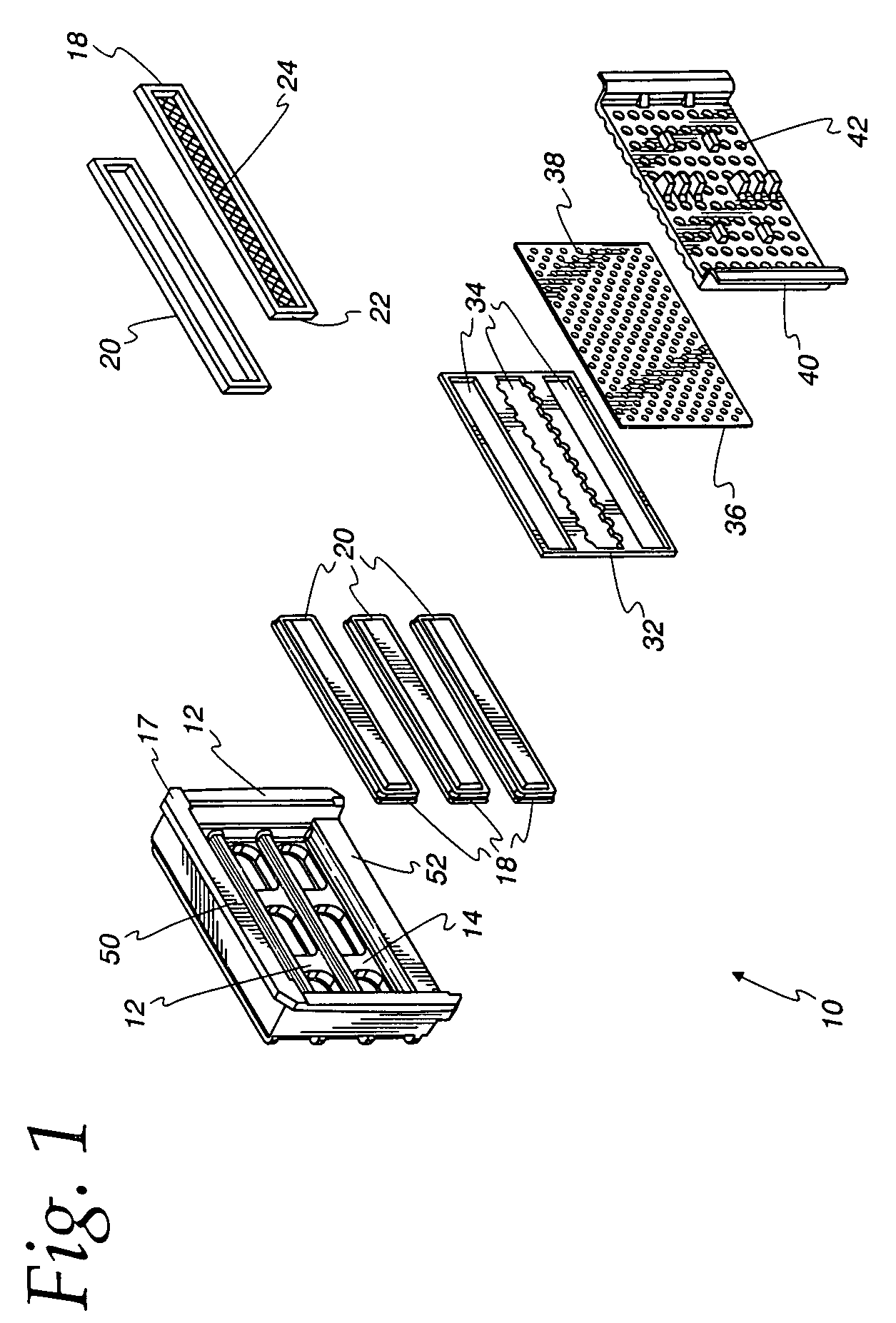
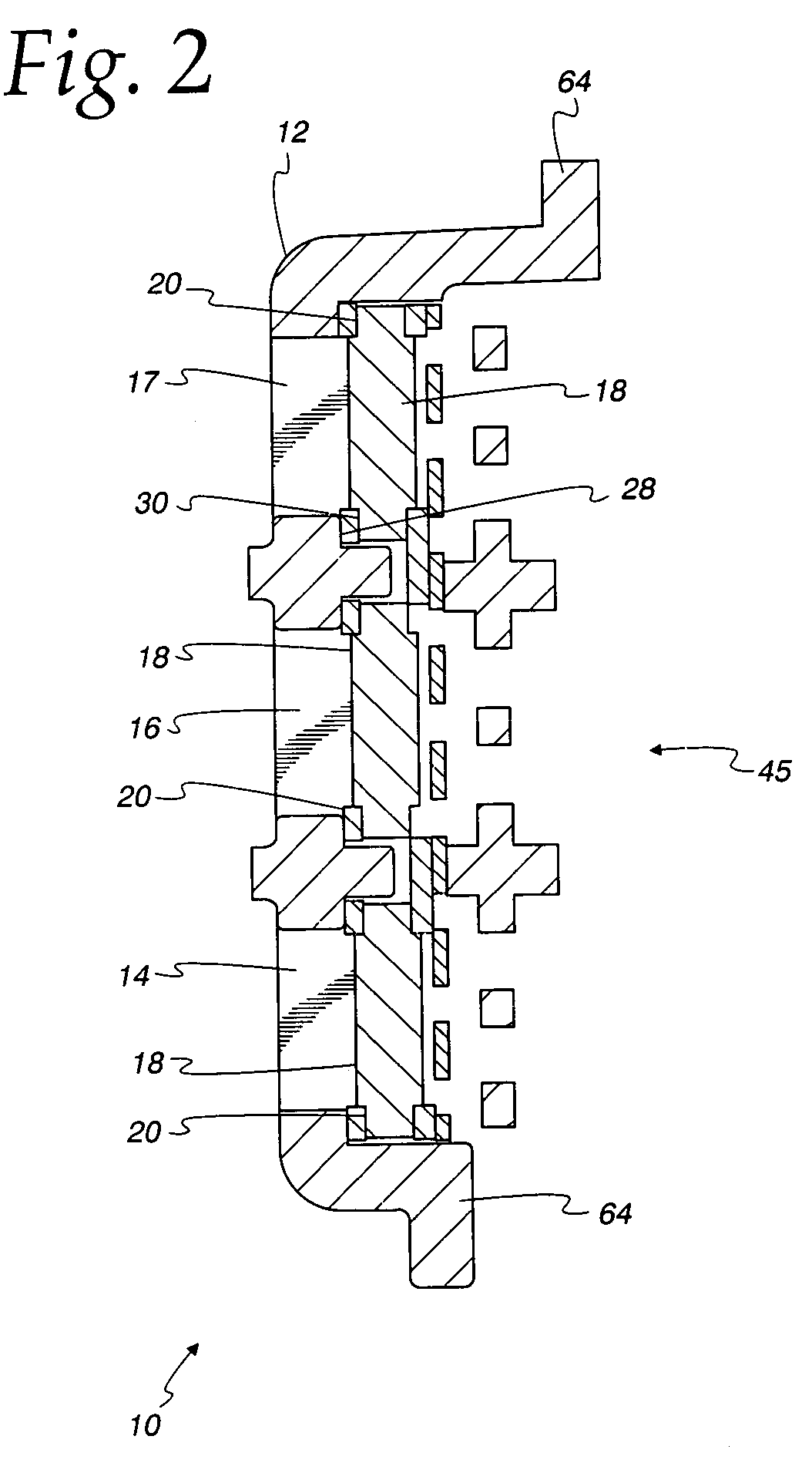
[0022]Referring to the drawings, and initially to FIG. 1, an improved circuit breaker arc chamber filter assembly is illustrated, and indicated generally by the reference numeral 10. The assembly 10 includes a filter frame or filter cup element 12 which has one or more generally rectilinear recesses 14, 16, for receiving complementary generally rectilinear shaped filter elements 18, each of which is additionally provided with a sealing gasket 20. As best viewed in FIG. 2, both the gaskets 20 and filter elements 18 interfit within the recesses 14, 16 and 17 of the filter cup or housing 12 so as to promote sealing engagement of the gaskets 20 between opposed and facing surfaces 28, 30 of the housing or cup 12 and the filter elements 20.

[0023]In accordance with one aspect of the invention, each of the filters 18 is separately mounted within an associated recess of the housing or cup 12 to define or provide a composite filter. Advantageously, by separating the filter into multiple piece...


PUM


Abstract

An improved filter assembly for a circuit breaker includes a generally rectilinear filter housing having at least two filter mounting zones for receiving at least two filter assemblies, so as to define, in the aggregate, a filter assembly, and at least two filter assemblies configured for interfitting with the filter mounting zones of the filter housing, each filter assembly comprising a generally rectilinear filter body having a given peripheral configuration and a filter gasket configured for interfitting about a periphery of the filter body for sealingly engaging the filter body relative to the filter housing in response to forces encountered by the filter assembly both upon assembly and in operation. The filter assembly may further have a small hole diffuser having a peripheral configuration similar to the peripheral configuration of the filter bodies, in the aggregate, when assembled with the filter housing and configured for interfitting within the filter housing.

Description

FIELD OF THE INVENTION[0001]This invention is directed generally to improvements in circuit breakers and more particularly to an improved circuit breaker arc chamber filter assembly and the manner of assembly thereof with an arc stack and breaker case.BACKGROUND OF THE INVENTION[0002]Low-voltage circuit breakers having high ratings generally utilize separable contacts arranged at the entry of an arc extinguishing chamber. When the contacts separate or open in response to a trip device following an overcurrent or the like, an electrical arc arises between the contacts. The arc extinguishing chamber is designed to absorb the energy of the arc while maintaining its voltage. Both the chamber and the separable contacts may be subject to high thermal, mechanical and electrical stresses. For example, a current of as much as 200,000 amperes may be maintained for 4 milliseconds at an arcing voltage of 500 volts, resulting in an energy of 400 kilojoules. The plasma column forming this arc can...

Claims


Application Information

Patent Timeline
Patent Type & Authority Patents(United States)
IPC IPC(8): H01H33/04H01H9/34
CPCH01H9/342
Inventor FABER, TIMOTHY R.MAULANDI, AYMON A.RIVAL, MARC F. J.PEARSON, DAVID R.
Owner SQUARE D CO
Why Eureka
Try Eureka