Two-by-two optical routing element using two-position MEMS mirrors

a technology of optical routing and mirror, applied in the field of fiberoptic communication, can solve the problems of difficult and expensive scaling of dwdm networks using sonet/sdh technology, and the explosion of global bandwidth demand, and achieve the effect of flexible and effective routing of spectral bands

Inactive Publication Date: 2007-02-13
ALTERA CORP
View PDF28 Cites 17 Cited by
  • Summary
  • Abstract
  • Description
  • Claims
  • Application Information

AI Technical Summary

Benefits of technology

[0007]The present invention provides a wavelength router that allows flexible and effective routing of spectral bands between a pair of input ports and a pair of output ports.

Problems solved by technology

The Internet and data communications are causing an explosion in the global demand for bandwidth.
This makes it difficult and expensive to scale DWDM networks using SONET / SDH technology.

Method used


Image

  • Two-by-two optical routing element using two-position MEMS mirrors
  • Two-by-two optical routing element using two-position MEMS mirrors
  • Two-by-two optical routing element using two-position MEMS mirrors

Examples


Embodiment Construction

1. Introduction

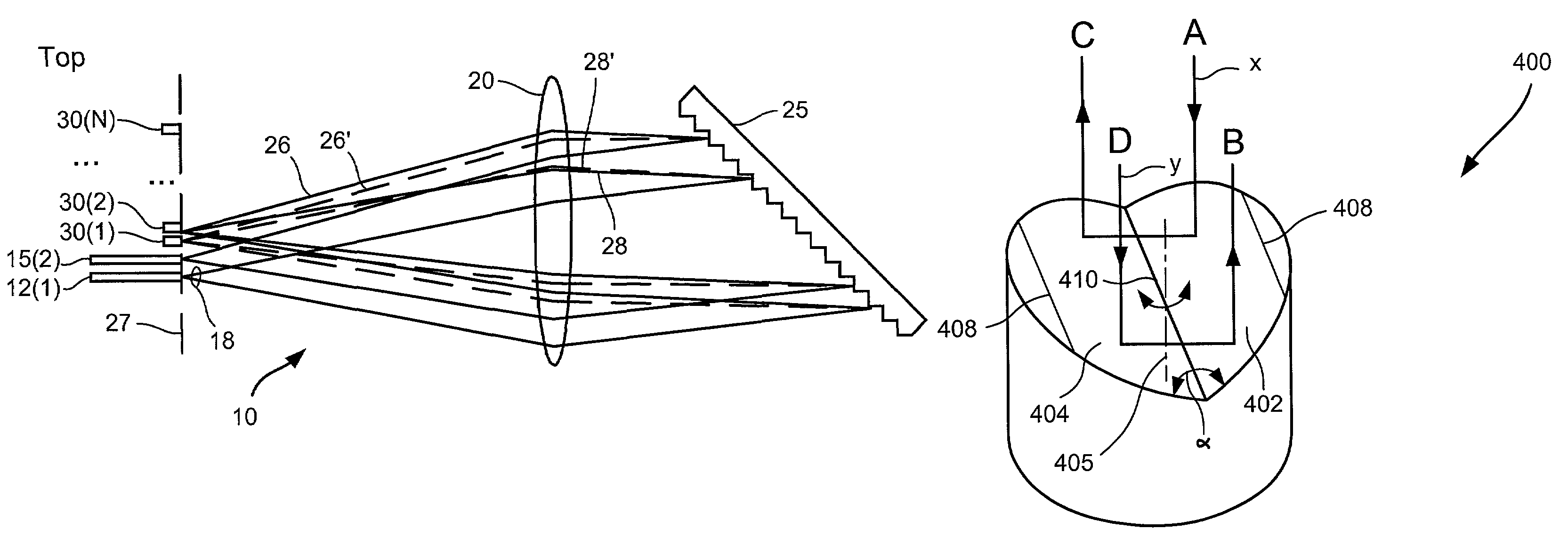
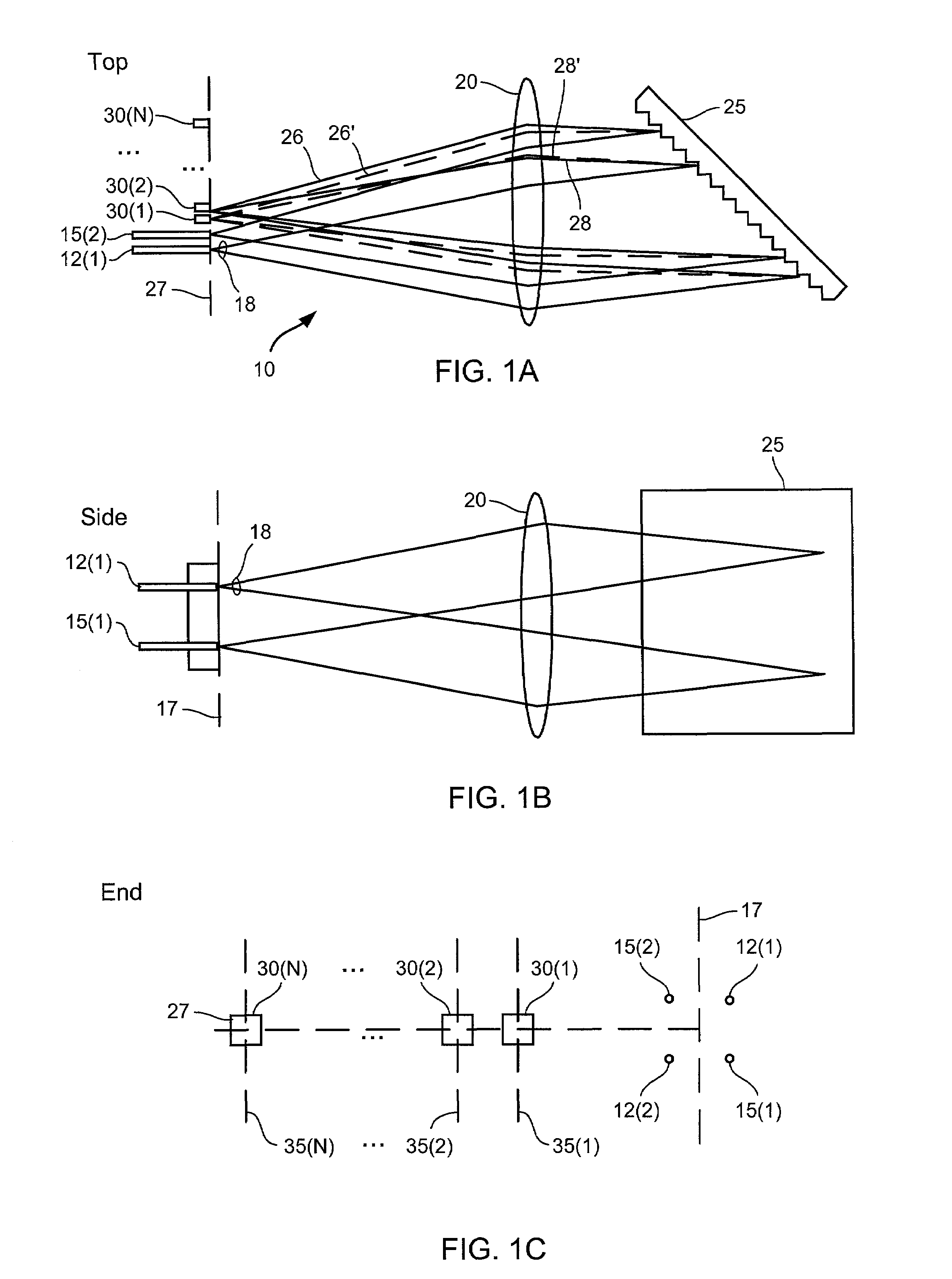
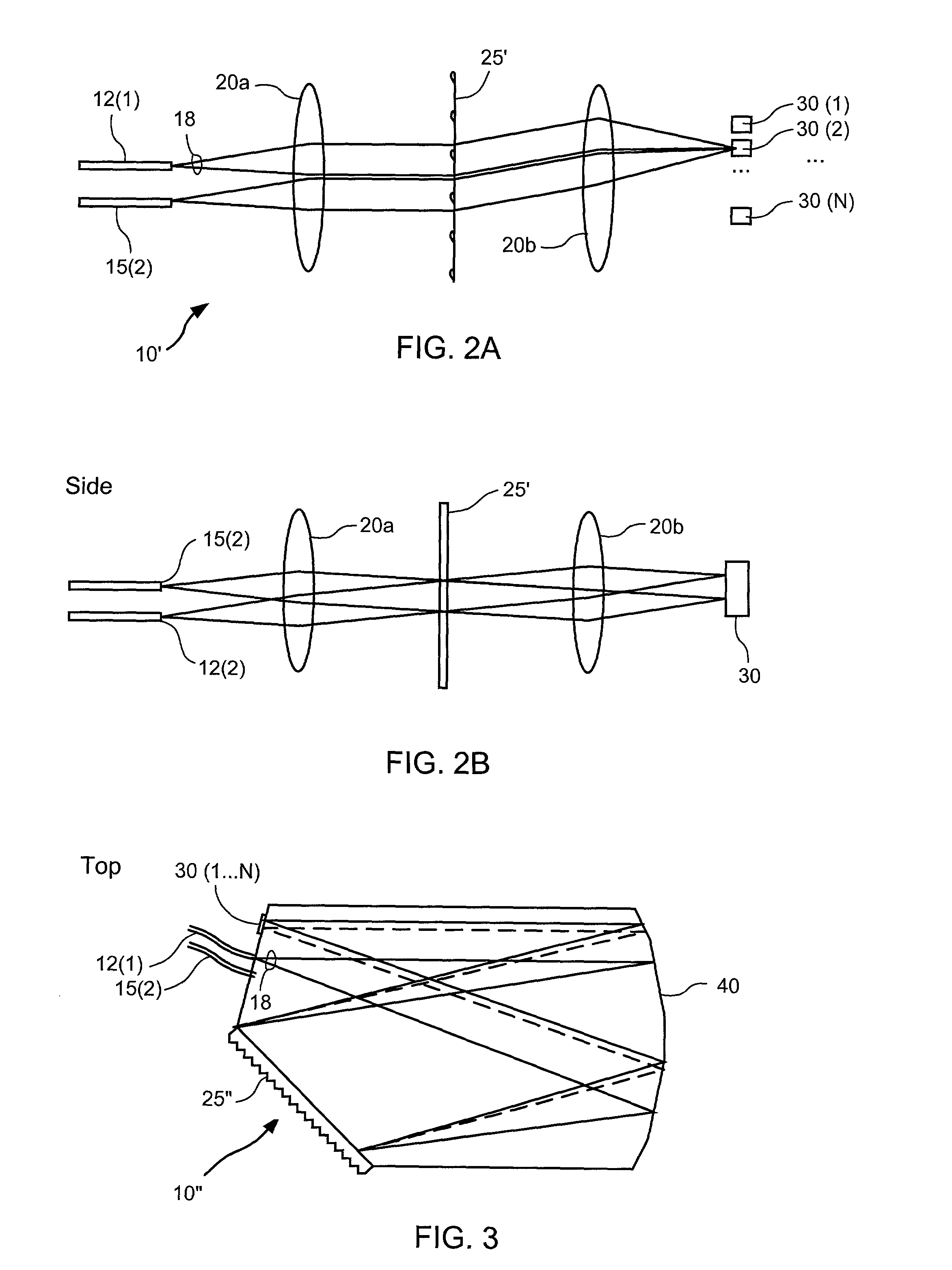
[0025]The following description sets forth embodiments of an optical routing element according to the invention. The general functionality of the optical routing element is to accept two optical signals, each having a plurality of (say N) spectral bands at a pair of input ports, and to direct the spectral bands according to their individual wavelengths to either of a pair of output ports. Embodiments generally include a free-space optical train to provide optical paths for the spectral bands and a routing mechanism that includes a plurality of dynamically configurable retroreflecting elements arranged to route the individual spectral bands as desired. As used herein, a “retroreflecting element” causes an incident optical ray to be directed along a path having a projection on the path of the incident ray that is opposite in direction to the incident path. In a special case, the redirected and incident paths are parallel but opposite in direction.

[0026]The term “free sp...


PUM


Abstract

Retroreflecting elements adapted for use in two-by-two optical routing elements. Each retroreflecting element is configured to selectively retroreflect two optical rays. A first reflective surface, such as may be provided by a mirror, is inclined with respect to a reference plane. A second reflective surface, such as may also be provided by a mirror, is opposed to and inclined with respect to the first reflective surface. The two surfaces are configured for rotation about an axis to multiple positions such that in a first position, a first ray is retroreflected along a first path and second ray is reflected along a second path, and in a second position, the first ray is reflected along the second path and the second ray is reflected along the first path.

Description

CROSS REFERENCES TO RELATED APPLICATIONS[0001]This application is related to commonly assigned, concurrently filed U.S. patent application Ser. No. 10 / 099,392, entitled “ONE-TO-M WAVELENGTH ROUTING ELEMENT” by Nicholas Charles Cizek et al., the entire disclosure of which is herein incorporated by reference for all purposes.BACKGROUND OF THE INVENTION[0002]This application relates generally to fiber-optic communications. This application relates more specifically to techniques and devices for routing different spectral bands of an optical beam.[0003]The Internet and data communications are causing an explosion in the global demand for bandwidth. Fiber optic telecommunications systems are currently deploying a relatively new technology called dense wavelength division multiplexing (DWDM) to expand the capacity of new and existing optical fiber systems to help satisfy this demand. In DWDM, multiple wavelengths of light simultaneously transport information through a single optical fiber...

Claims


Application Information

Patent Timeline
Patent Type & Authority Patents(United States)
IPC IPC(8): G02B6/26G02B6/35G02B6/04G02B6/34
CPCG02B6/29307G02B6/2931G02B6/3568G02B6/352G02B6/04G02B6/266G02B6/357G02B6/3546G02B6/356
Inventor CIZEK, NICHOLAS CHARLES
Owner ALTERA CORP
Why Eureka
Try Eureka