Coplanar waveguide feeding-based semi-ring-shaped surface wave transmission line and power splitter

A coplanar waveguide and semi-circular technology, which is applied in the direction of waveguide devices, circuits, electrical components, etc., can solve the problems of inability to integrate surface waves and microstrip circuits

Active Publication Date: 2017-05-24
SOUTH CHINA UNIV OF TECH
View PDF8 Cites 3 Cited by
  • Summary
  • Abstract
  • Description
  • Claims
  • Application Information

AI Technical Summary

Problems solved by technology

[0007] The above-mentioned existing technologies all use the microstrip line to the surface structure. Since the microstrip line cannot be a single-layer metal, it must have a bottom metal ground, so the surface wave and the microstrip circuit cannot be integrated in one plane.

Method used


Image

  • Coplanar waveguide feeding-based semi-ring-shaped surface wave transmission line and power splitter
  • Coplanar waveguide feeding-based semi-ring-shaped surface wave transmission line and power splitter

Examples


Embodiment 1

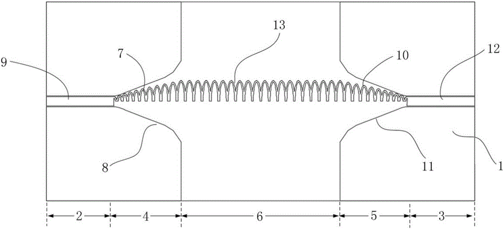
[0041] Such as figure 1 As shown, the surface wave transmission line of this embodiment includes a dielectric substrate 1, a first coplanar waveguide 2, a second coplanar waveguide 3, a first transition structure 4, a second transition structure 5 and a semi-annular surface wave structure 6. The first coplanar waveguide 2, the second coplanar waveguide 3, the first transition structure 4, the second transition structure 5 and the semi-annular surface wave structure 6 are arranged on the same layer of the dielectric substrate 1, and in this embodiment are arranged on the top layer , the bottom layer of the dielectric substrate 1 has no copper clad ground; the first coplanar waveguide 2 and the second coplanar waveguide 3 are left-right symmetrical, and the first transition structure 4 and the second transition structure 5 are left-right symmetrical.

[0042] The first transition structure 4 includes a plurality of first semi-annular transition units 7 and first metal units 8 lo...

Embodiment 2

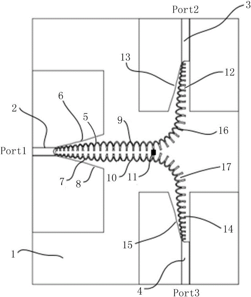
[0046] Such as figure 2 As shown, the surface wave power splitter of this embodiment includes a dielectric substrate 1, a first coplanar waveguide 2, a second coplanar waveguide 3, a third coplanar waveguide 4, a first transition structure, a second transition structure, a third The transition structure, the fourth transition structure, the first semi-annular surface wave structure, the second semi-annular surface wave structure, the third semi-annular surface wave structure and the fourth semi-annular surface wave structure, the first coplanar waveguide 2, the second Two coplanar waveguides 3, third coplanar waveguides 4, first transition structure, second transition structure, third transition structure, fourth transition structure, first semi-annular surface wave structure, second semi-annular surface wave structure, and second semi-annular surface wave structure The three-half annular surface wave structure and the fourth half-annular surface wave structure are arranged o...


PUM


Abstract

The present invention discloses a coplanar waveguide feeding-based semi-ring-shaped surface wave transmission line and power splitter. The transmission line comprises a dielectric substrate, a first coplanar waveguide, a second coplanar waveguide, a first transition structure, a second transition structure and a semi-ring-shaped surface wave structure; the first coplanar waveguide, the second coplanar waveguide, the first transition structure, the second transition structure and the semi-ring-shaped surface wave structure are arranged on the same layer of the dielectric substrate; the first coplanar waveguide and the second coplanar waveguide are in bilateral symmetry; the first transition structure and the second transition structure are in bilateral symmetry; the first coplanar waveguide is connected with the left end of the semi-ring-shaped surface wave structure through the first transition structure; and the second coplanar waveguide is connected with the right end of the semi-ring-shaped surface wave structure through the second transition structure. With the transmission line and power splitter of the invention adopted, the conversion of TEM waves to surface waves can be realized under a condition that the dielectric substrate has no bottom metal ground, and electromagnetic waves can be transmitted with low loss.

Description

technical field [0001] The invention relates to a transmission line and a power divider, in particular to a coplanar waveguide-fed semi-annular surface wave transmission line and a power divider, which belong to the technical field of integrated circuits and surface waves. Background technique [0002] Surface wave transmission can realize high-frequency electromagnetic wave transmission of a single conductor, which has good bendability and easy processing, and can realize low-loss electromagnetic wave transmission. In the future communication technology, the surface wave structure can achieve high integration and miniaturization, which has great application value for the communication industry and the integrated circuit industry. [0003] According to investigation and understanding, the existing technologies that have been disclosed are as follows: [0004] 1) The invention patent with the Chinese patent number 201310222354.6 discloses a device for mutual conversion betwe...

Claims


Application Information

Patent Timeline
Patent Type & Authority Applications(China)
IPC IPC(8): H01P5/08H01P5/12
CPCH01P5/08H01P5/12
Inventor 王世伟邓飞
Owner SOUTH CHINA UNIV OF TECH
Why Eureka
Try Eureka