Method for monitoring pouring compactness of self-compacting concrete in large-scale structural module wall

A self-compacting concrete, large-scale structure technology, applied in measuring devices, material analysis by electromagnetic means, instruments, etc., can solve the problems of difficult repair, difficult equipment layout, complex steel structure, etc. Space-constrained, accurate results

Active Publication Date: 2014-11-19
SHANGHAI NUCLEAR ENG RES & DESIGN INST CO LTD
View PDF4 Cites 4 Cited by
  • Summary
  • Abstract
  • Description
  • Claims
  • Application Information

AI Technical Summary

Problems solved by technology

Tests have proved that due to the complex structures such as shear studs and section steel inside the structural module, and the fact that the concrete itself is a heterogeneous material, the results of ultrasonic testin

Method used


Image

  • Method for monitoring pouring compactness of self-compacting concrete in large-scale structural module wall
  • Method for monitoring pouring compactness of self-compacting concrete in large-scale structural module wall

Examples


Example Embodiment

[0018] Example 1

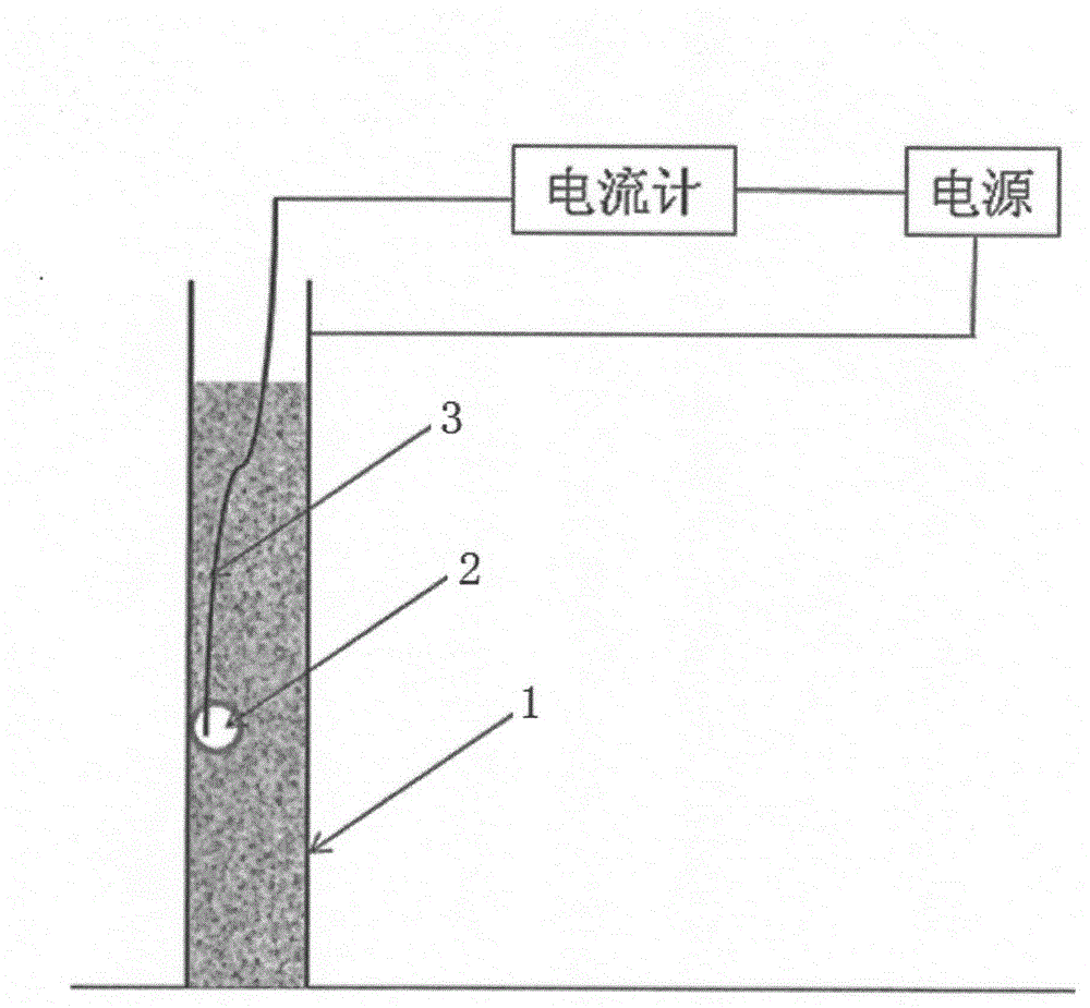
[0019] Such as figure 1 As shown, the steps of a method for monitoring the pouring compactness of self-compacting concrete inside a large structural module wall of a nuclear power plant disclosed in this embodiment are:

[0020] Step 1: Before pouring self-compacting concrete in the wall 1 of the large structural module of the nuclear power plant, judge that there may be a hidden danger area 2 of the wall 1 that is not dense;

[0021] The second step is to embed 0.3mm in the wall 1 2 Cable 3, one end of the cable 3 is located in the area 2 where there may be hidden dangers of compaction. At the same time, the end of the cable 3 does not touch the body of the large structural module, and the other end of the cable 3 is led out of the wall 1;

[0022] Step 3. In the process of pouring self-compacting concrete in the wall 1, when the hidden danger area 2 is or is covered by self-compacting concrete, connect an external power supply in series with the end of the cable 3 ...

Example Embodiment

[0024] Example 2

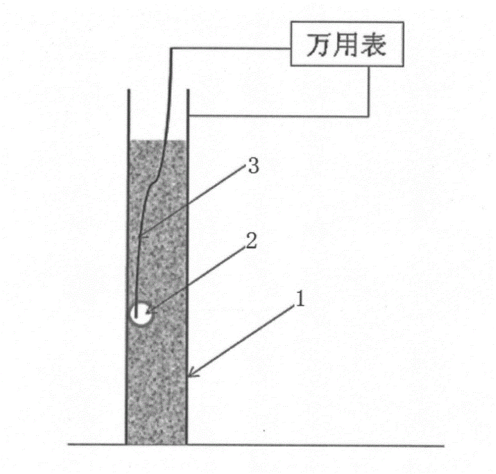
[0025] Such as figure 2 As shown, the difference between the method for monitoring the pouring compactness of self-compacting concrete inside the wall of the large-scale structural module of a nuclear power plant disclosed in this embodiment and the first embodiment is that:

[0026] In the third step, a multimeter is connected to the end of the cable 3 leading out of the wall 1 to form a loop.

[0027] The fourth step is changed to: Observe the resistance value measured by a multimeter. If the resistance is small, it means that the concrete in the area 2 where there may be a hidden danger of incompactness has been compacted, and if the resistance approaches infinity, it means that there may be a hidden danger of inconsistency. The concrete in area 2 is not compacted. Use a method of slightly disturbing members such as steel bars in area 2 until the resistance value measured by a multimeter is significantly reduced, which proves that the concrete in area 2 is com...


PUM


Abstract

Monitoring on pouring compactness of self-compacting concrete in a large-scale structural module wall of an AP/CAP serial three-generation nuclear power plant is the construction difficult problem which is not completely effectively solved so far and currently, a method for determining compactness of the concrete in a large-scale structural module mainly adopts ultrasonic detection. Experiments prove that an ultrasonic detection result is not ideal very much due to complex structures inside the structural module, such as a shear concrete stud and a section steel, and a heterogenous material forming the concrete. Moreover, ultrasonic detection equipment is large, is difficult to place in a narrow space, is unsuitable to monitor in the construction process and is mostly detected afterwards; if the condition that the concrete is not compact is generated, the rework is difficult. A method disclosed by the invention adopts a mode of detecting a current or a resistance through a closed circuit loop, can monitor the compactness condition and timely rectify in the pouring process and has the advantages of simplicity and sensitivity for operation, accurate result and the like.

Description

Technical field [0001] The invention relates to a method for monitoring the compactness of self-compacting concrete pouring inside a large structural module wall of a nuclear power plant. Background technique [0002] The AP / CAP series pressurized water reactor nuclear power technology is one of the most advanced third-generation nuclear power technologies in the world. Modular construction technology is one of the major features of the AP / CAP nuclear power technology. Modularization can save construction time to the greatest extent. This technology uses a series of large steel structure modules, such as CA01, CA02, CA03, CA04, CA20, etc. The internal structure of this type of steel structure module wall is complex, and the pouring concrete inside the wall is self-compacting concrete, which cannot be vibrated with a vibrating rod. If the method is not properly controlled, the internal concrete will be difficult to compact, mainly in the following four types of parts: 1) The area...

Claims


Application Information

Patent Timeline
IPC IPC(8): G01N27/00G01N27/04
Inventor 韩飞
Owner SHANGHAI NUCLEAR ENG RES & DESIGN INST CO LTD
Why Eureka
Try Eureka