Image forming apparatus and method

a technology of image forming apparatus and forming machine, which is applied in the direction of electrographic process apparatus, thin material processing, instruments, etc., can solve the problems of inability to correctly determine the distance b [mm] between the rear edge of the sheet and the register mark, and the processing time is too long

Inactive Publication Date: 2007-02-13
FUJIFILM BUSINESS INNOVATION CORP
View PDF10 Cites 84 Cited by
  • Summary
  • Abstract
  • Description
  • Claims
  • Application Information

AI Technical Summary

Benefits of technology

[0013]The image forming apparatus further includes a registration roll for transporting the sheet to the transfer unit when the image is transferred to the second side, and the image detection sensor is characterized in that a distance to the transfer unit in the transfer member is longer than the distance between the registration roll and the transfer unit. The control unit controls the rotation timing of the registration roll for transporting the sheet to the transfer unit, thereby controlling the timing of feeding the sheet.
[0014]On the other hand, in the image forming apparatus to which the present invention is applied, the control unit controls the timing of writing the image formed on the second side on the basis of a distance measured by the first side read sensor. The reference image formed on the first side is a register mark, and the control unit controls the timing of writing the image in a direction that brings the register mark formed on the first side and a register mark newly formed on the second side into positional match in terms of the surface and the back.
[0015]From other standpoints, the present invention is an image forming apparatus that reverses a sheet on a first side of which an image is formed, using reversion transportation paths, and forms an image on a second side of the reversed sheet, wherein, when an image is formed on the first side, a reference image printing part prints a predetermined reference image at a predetermined distance from the rear edge of the first side, using a color component that is difficult for human eyes to identify; a distance measurement part measures a distance between the rear edge of the first side and the reference image with respect to the sheet on which the reference image is printed by the reference image printing part and which is reversed in the reversion transportation paths; and a control part, when an image is formed on the second side, controls the timing of feeding the sheet or the timing of writing the image on the basis of the distance measured by the distance measurement part.

Problems solved by technology

For this reason, excessively long processing time has been problematic.
On the other hand, the distance b [mm] between the rear edge of a sheet and a register mark cannot be correctly determined because of an error (e.g., ±1 mm) of sheet lengths, a belt speed error during image writing, and variations in sheet transportation speeds.
If the register marks do not match positionally, a positional mismatch between the surface and the back will cause great problems such as a reference position that cannot be determined when sheets are cut at their ends, and column mismatch between opened pages during bookbinding and the like.
However, an error of sheet lengths cannot be determined in advance.
Therefore, it is difficult to control registration in advance.
For this reason, with the prior arts, it has been impossible to register the surface and the back of sheets with great precision.

Method used


Image

  • Image forming apparatus and method
  • Image forming apparatus and method
  • Image forming apparatus and method

Examples


Embodiment Construction

[0026]Hereinafter, embodiments of the present invention will be described in detail with reference to the accompanying drawings.

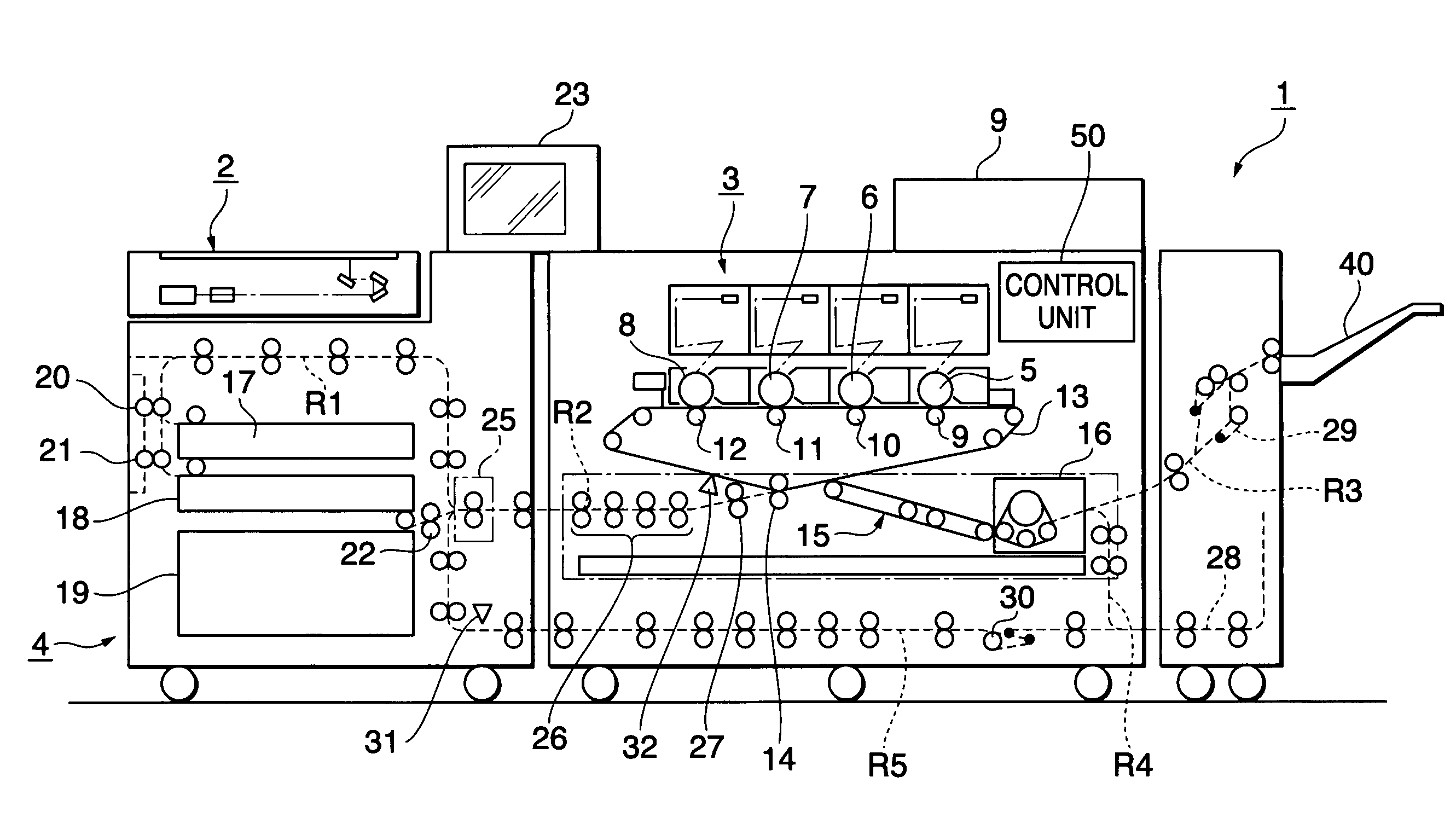
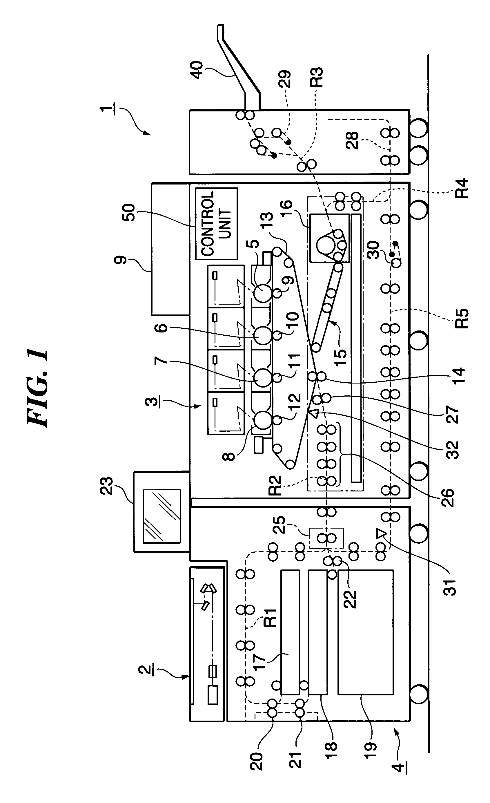
[0027]FIG. 1 is a diagram showing an overall configuration of an image forming apparatus 1 to which this embodiment is applied. The image forming apparatus capable of outputting full-color images primarily includes: an image read unit 2 that reads an image of an original; an image forming unit 3 that forms an image on a sheet; and a sheet feeding unit 4 that feeds the sheet to the image forming unit 3. The image forming apparatus 1 has a control unit 50 that controls the whole of the image forming apparatus 1.

[0028]The image read unit 2 reads an image of an original set on a transparent original base. It includes: an optical scanning system having, e.g., a lamp, mirror, carriage, and the like; a lens system for forming an optical image scanned by the optical scanning system; and an image read sensor such as CCD that receives the optical image formed by the ...


PUM


Abstract

An image forming apparatus registers both sides of sheets with great precision in a sheet transportation direction in both-side image formation. The image forming apparatus includes: photoconductive drums holding toner images; an intermediate transfer belt temporarily holding the toner images; a secondary transfer roll that transfers the toner images to a sheet in a transfer unit; a registration roll rotating toward the transfer unit being in sheet feeding timing; a fixing unit fixing the toner images transferred to a first side of the sheet; reversion transportation paths reversing the sheet and again transporting the sheet to the transfer unit; a first sensor detecting the image of the first side of the sheet; and a second sensor that detects the toner images held in the intermediate transfer belt.

Description

BACKGROUND OF THE INVENTION[0001]1. Field of the Invention[0002]The present invention relates to an image forming apparatus and method used for a copier, facsimile, and printer, and more particularly to an image forming apparatus having a double side image formation mode in which images are formed on both sides of a sheet and a method therefor.[0003]2. Description of Related Art[0004]Image forming apparatuses such as printers, copiers, and facsimiles are proposed to be of full-color, tandem type to form color images at high speed and with high quality. A typical tandem image forming apparatus includes four image forming units for yellow (Y), magenta (M), cyan (C), and black (K) disposed in parallel to each other in which toner images of yellow, magenta, cyan, and black are successively formed, transfers (primary transfer) the toner images onto an intermediate transfer belt serving as an intermediate transfer member, then collectively transfers (secondary transfer) the toner images f...

Claims


Application Information

Patent Timeline
Patent Type & Authority Patents(United States)
IPC IPC(8): G03G15/00B65H9/14G03G21/14B65H15/00G03G15/23
CPCG03G15/231G03G2215/0119G03G2215/00599
Inventor MATSUZAKA, SATOSHIYAMAMOTO, KEIJITORIMARU, SATORUKAWABATA, TAKASHITAKAHASHI, MASAAKIMIYAMOTO, YOKOKANEYAMA, KIYOTOSHIKIKUCHIHARA, KATSUNORI
Owner FUJIFILM BUSINESS INNOVATION CORP
Why Eureka
Try Eureka