Azimuth measuring device and azimuth measuring method

a technology of azimuth and measuring device, which is applied in wave based measurement systems, instruments, and reradiation, etc., can solve problems such as limited range in orientation change, and achieve the effect of reducing load on the user

Inactive Publication Date: 2007-02-13
ASAHI KASEI ELECTRONICS CO LTD
View PDF12 Cites 43 Cited by
  • Summary
  • Abstract
  • Description
  • Claims
  • Application Information

AI Technical Summary

Benefits of technology

[0021]By so doing, simply changing the orientation of the measuring device on a predetermined plane arbitrarily or three-dimensionally arbitrarily allows offset information of the detection means with respect to each axis output to be calculated.
[0054]This allows the user to realize offset calibration without the user being aware of the offset calibration, making it possible to reduce load on the user in calibrating the offset.

Problems solved by technology

Here, calculating offset information simply requires the orientation of the measuring device to be changed and the range in which the orientation changes may be limited.

Method used


Image

  • Azimuth measuring device and azimuth measuring method
  • Azimuth measuring device and azimuth measuring method
  • Azimuth measuring device and azimuth measuring method

Examples


Embodiment Construction

[0075]With reference now to the attached drawings, an azimuth measuring device and azimuth measuring method according to embodiments of the present invention will be explained below.

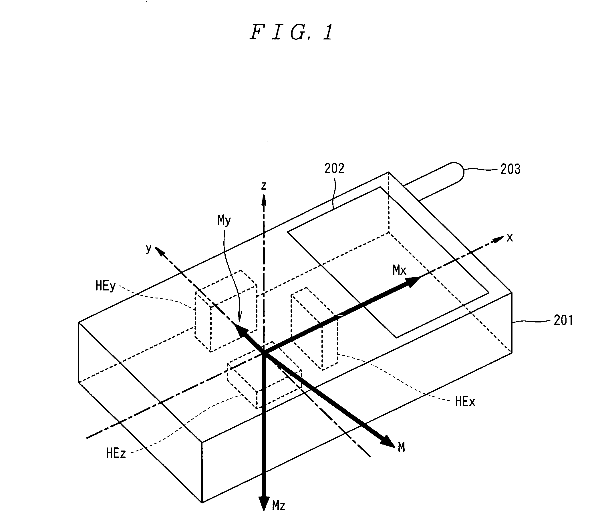
[0076]FIG. 1 is a perspective view showing an overall structure of a portable device according to an embodiment of the present invention.

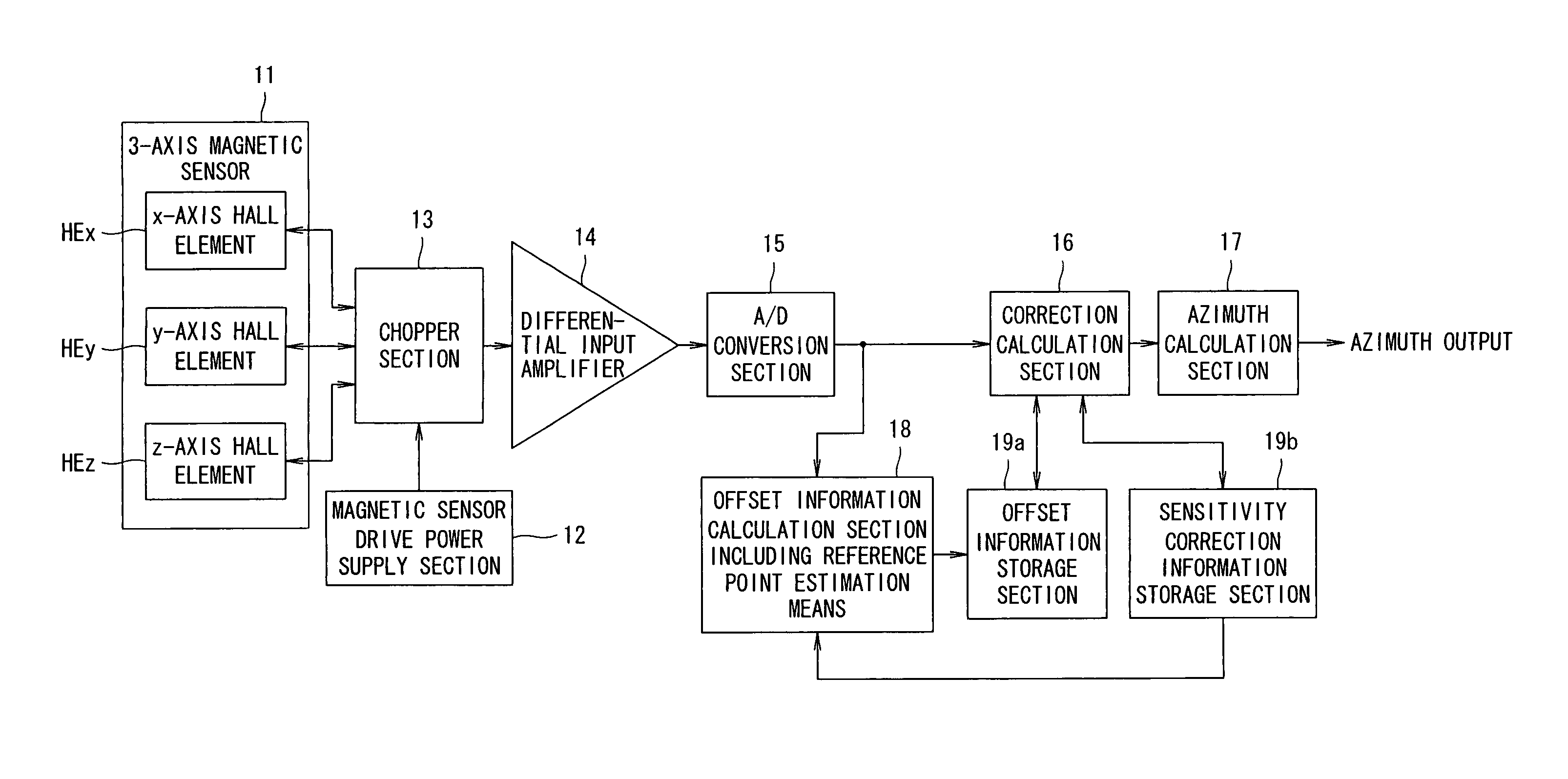
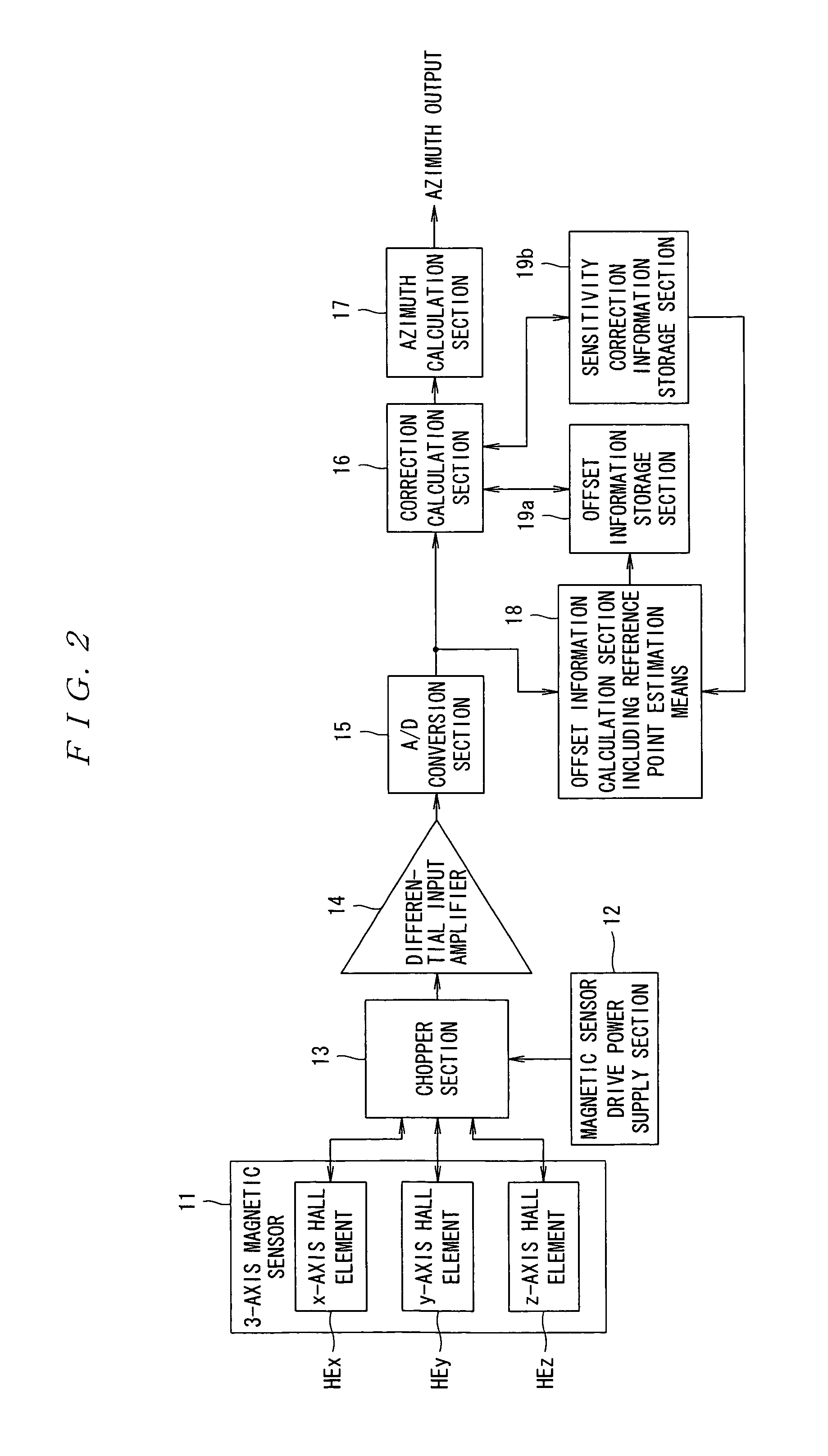
[0077]In FIG. 1, a portable device 201 is provided with a display section 202 and an antenna 203 and incorporates an azimuth measuring device which measures earth magnetism on three axes to obtain azimuth.

[0078]Here, the azimuth measuring device is provided with an x-axis Hall element HEx which measures an x-direction component Mx of earth magnetism M, a y-axis Hall element HEy which measures a y-direction component My of earth magnetism M and a z-axis Hall element HEz which measures a z-direction component Mz of earth magnetism M, and the x-axis Hall element HEx, y-axis Hall element HEy and z-axis Hall element HEz are arranged in such a way that their respective magnet...


PUM


Abstract

An azimuth measuring device capable of calibrating a magnetic sensor without putting load on a user is provided. When a point having amplified output values Sx, Sy, Sz after a sensitivity correction as x, y, z components is arranged on an xyz coordinate system, an offset information calculation section 8 calculates the center coordinates of such a sphere whose surface is located in the vicinity of each point and calculates an x component of the center coordinates of this sphere as a current offset Cx of an x-axis Hall element HEx, a y component of the center coordinates of this sphere as a current offset Cy of a y-axis Hall element HEy and a z component of the center coordinates of this sphere as a current offset Cz of a z-axis Hall element HEz. It is thereby possible to calibrate the magnetic sensor without putting load on the user.

Description

TECHNICAL FIELD[0001]The present invention relates to an azimuth measuring device and azimuth measuring method, and is preferably applicable to offset corrections of a magnetic sensor in particular.BACKGROUND ART[0002]An azimuth measuring device which arranges magnetic sensors in two or three directions, measures earth magnetism using the magnetic sensors in the respective directions and measures azimuth is known.[0003]When a magnetized part such as a speaker is placed near the magnetic sensors of such an azimuth measuring device, an offset is produced in the outputs of the magnetic sensors due to a magnetic field leaking from the magnetized part.[0004]In order to prevent errors from occurring in azimuth calculations due to the offset of the magnetic sensors, the above described azimuth measuring device needs to carry out calibration on the azimuth measuring device for the purpose of correcting the offset of the magnetic sensors.[0005]Therefore, a conventional azimuth measuring devi...

Claims


Application Information

Patent Timeline
Patent Type & Authority Patents(United States)
IPC IPC(8): G06F15/00G01S13/08G01C17/28G01C17/38
CPCG01C17/38G01C17/28G01C17/30
Inventor HIKIDA, KOICHIYAMASHITA, MASAYA
Owner ASAHI KASEI ELECTRONICS CO LTD
Why Eureka
Try Eureka