Virtual impactor device with reduced fouling

a technology of virtual impactors and aerosols, which is applied in liquid degasification, instruments, separation processes, etc., can solve the problems of less navigating, high fouling of virtual impactor devices, and often so great fouling problems, so as to reduce waste, increase concentration efficiency, and prolong the useful life of virtual impactors

Inactive Publication Date: 2007-02-20
Q21 CORPORATION +2
View PDF20 Cites 27 Cited by
  • Summary
  • Abstract
  • Description
  • Claims
  • Application Information

AI Technical Summary

Benefits of technology

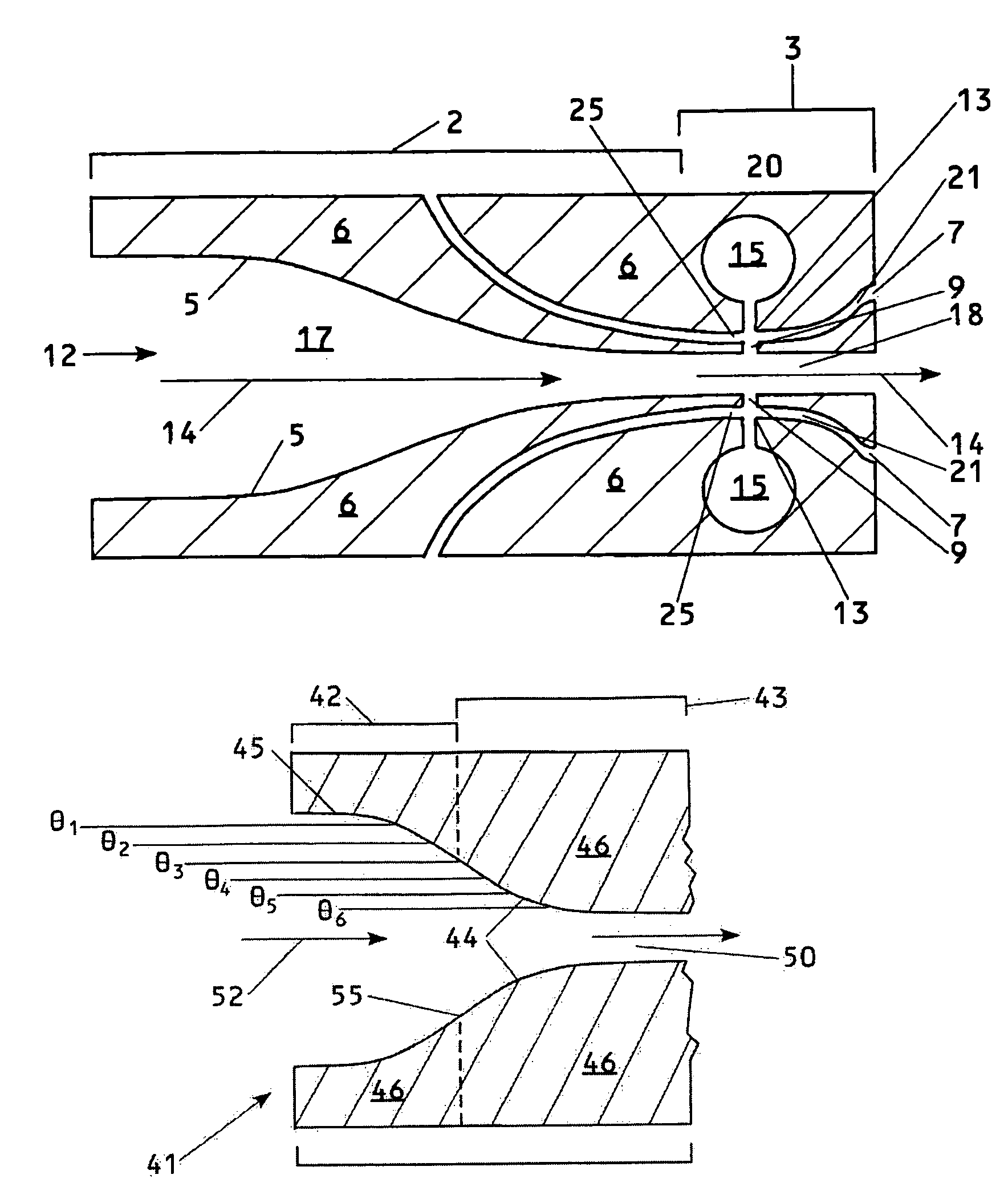
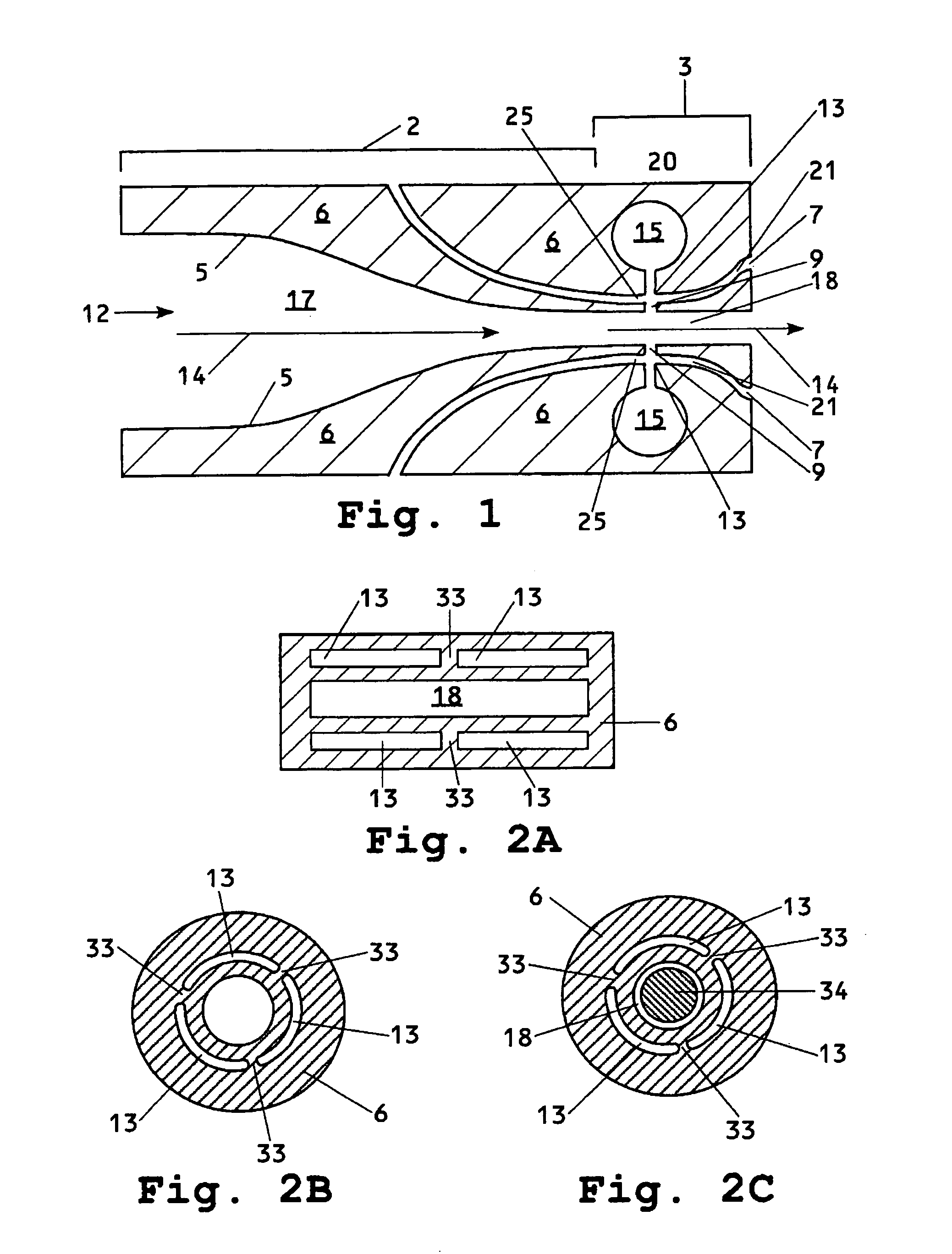
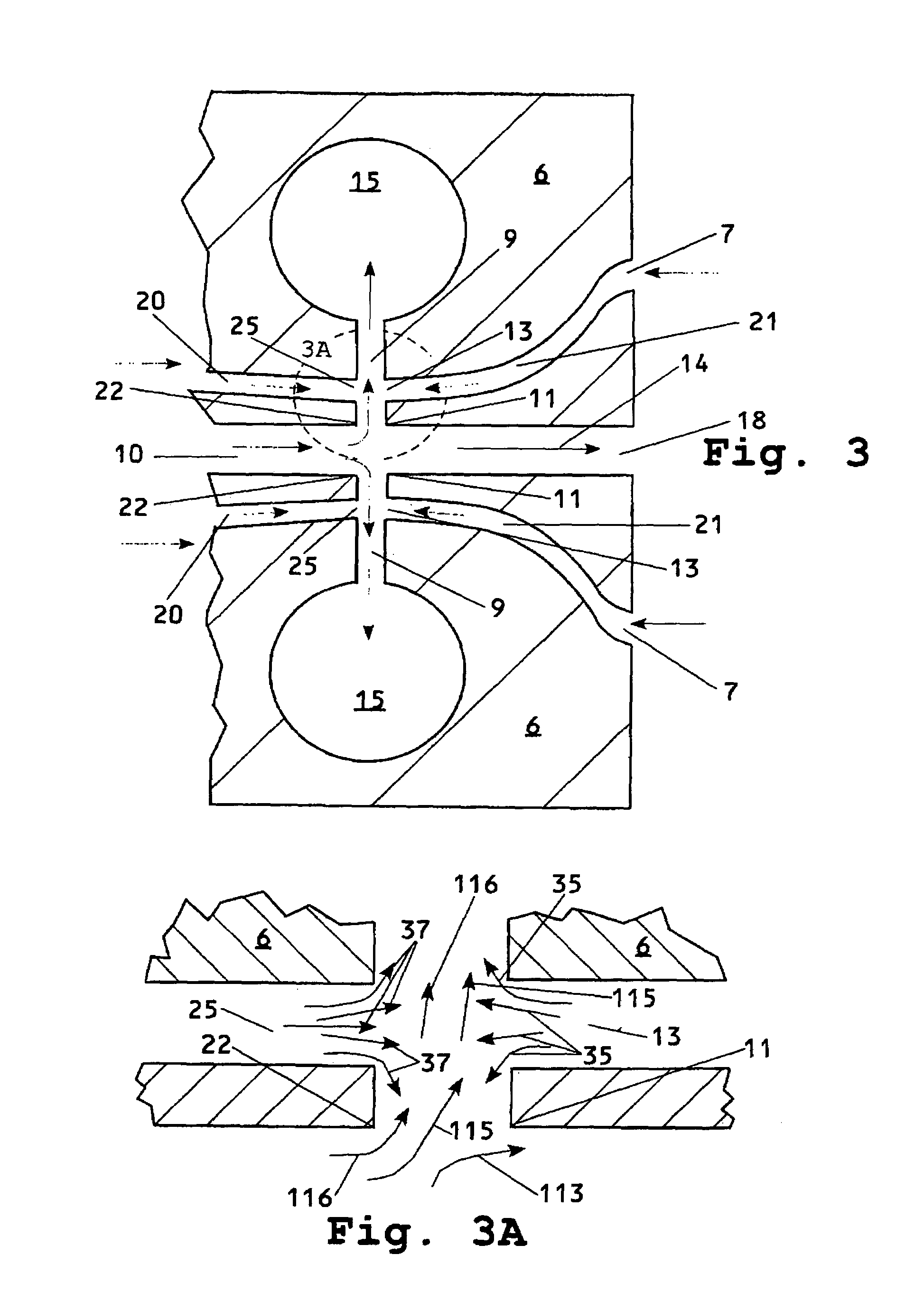
[0018]Injecting a fluid into the separation zone through the injection ports reduces fouling in the separation zone of the virtual impactor device. Although the invention is not limited to any theory, it is believed that the injected fluids direct the particle-laden fluid away from the interior surfaces of the separation zone, in effect helping to direct the fluid, together with the fluid-borne particles, toward the center of the major and minor flow outlets. This reduces the proportion of particles contacting the interior surfaces of the separation zone and thus reduces fouling.
[0028]Virtual impactor devices and acceleration nozzles of the invention are less prone to fouling due to collisions of particles with the interior surfaces. This allows for increased concentration efficiencies, longer useful life for the devices, reduced waste and reduced maintenance.

Problems solved by technology

The large inertia of the particles makes them less able to navigate this change in direction, and so this major flow contains a smaller particle concentration than either the original stream or the minor flow.
Virtual impactor devices are highly prone to fouling due to collisions of the particles with the side walls of the device.
The fouling problem is often so great that the virtual impactor device effectively functions like a filter, removing rather than concentrating the particles.

Method used


Image

  • Virtual impactor device with reduced fouling
  • Virtual impactor device with reduced fouling
  • Virtual impactor device with reduced fouling

Examples


example

[0103]A two-stage virtual impactor device is constructed as shown in FIG. 5. In the first stage, eight virtual impactor devices 70 are arranged vertically, in two groups of four. Each group of four first-stage virtual impactors are connected to a common inlet duct 50 and a common outlet duct 67. Each virtual impactor device 70 includes an acceleration nozzle 61, a major flow outlet 69 and a minor flow outlet 78. The second stage includes two vertically arranged virtual impactor devices 170 which include acceleration nozzles 161, major fluid outlets 160 and minor flow outlets 178. Each of the two second stage impactor devices accepts a stream from one set of four first stage virtual impactor devices. Fluid exiting through minor flow outlets 178 is separately withdrawn through ducts 65.

[0104]All of the virtual impactor devices 70 and 170 are of the same design. All are made by machining identical top and bottom halves from an aluminum block. The blocks are illustrated in FIGS. 6A and ...


PUM

PropertyMeasurementUnit
widthaaaaaaaaaa
widthaaaaaaaaaa
volume average particle diameteraaaaaaaaaa

Abstract

A virtual impactor device having reduced fouling includes injection ports within the separation zone to redirect particles that otherwise tend to impact the walls of the separation zone and produce fouling. The virtual impactor device preferably also includes an acceleration zone having concave and convex sections, which reduces fouling in that area. The virtual impactor device can be combined with various downstream components such as collectors, atomizers and various analytical devices.

Description

BACKGROUND OF THE INVENTION[0001]This invention relates to a virtual impactor type aerosol concentration or collection device.[0002]Virtual impactor particle collection devices are well-known, being described, for example in U.S. Pat. Nos. 4,767,524, 6,010,554, 6.120,573 and 6,290,065, among others. Generally, these consist of an acceleration nozzle, in which the flow path is constricted in order to increase flow velocity, and a separation zone located downstream from the acceleration nozzle, where the fluid stream is split into at least two channels. A minor (in terms of fluid volume) flow travels more or less in the original direction of flow (i.e., the direction of flow through the constriction). The inertia of the particles causes most of them to be carried off with this minor flow. A major flow containing most of the fluid is taken off at an angle to the original direction of flow. The large inertia of the particles makes them less able to navigate this change in direction, and...

Claims


Application Information

Patent Timeline
Patent Type & Authority Patents(United States)
IPC IPC(8): G01N1/00
CPCB01D19/0094G01N1/2208B01D21/283
Inventor SHEKARRIZ, ALIREZAMOORE, ROBERT REEDBIRMINGHAM, JOSEPH G.
Owner Q21 CORPORATION
Why Eureka
Try Eureka