Peripheral view speedometer

a technology of speedometer and face plate, which is applied in the direction of heat measurement, instruments, transportation and packaging, etc., can solve the problems of cumbersome mechanism, inability to achieve the desired effect, and increased chance of getting into a problem situation

Inactive Publication Date: 2007-02-20
RICHTER MILTON
View PDF9 Cites 26 Cited by
  • Summary
  • Abstract
  • Description
  • Claims
  • Application Information

AI Technical Summary

Benefits of technology

[0009]The present invention provides a speedometer face plate assembly that exhibits a smooth transition from one color to another of a logical color progression as the speed increases or decreas

Problems solved by technology

The availability of cruise control devices have made it easier to stay within acceptable speed limits, but many drivers fail to take advantage of such devices making it necessary that the driver constantly look at the speedometer in order to maintain proper speed.
The more often the driver's eyes are taken away from the road, the greater the cha

Method used


Image

  • Peripheral view speedometer
  • Peripheral view speedometer
  • Peripheral view speedometer

Examples


Embodiment Construction

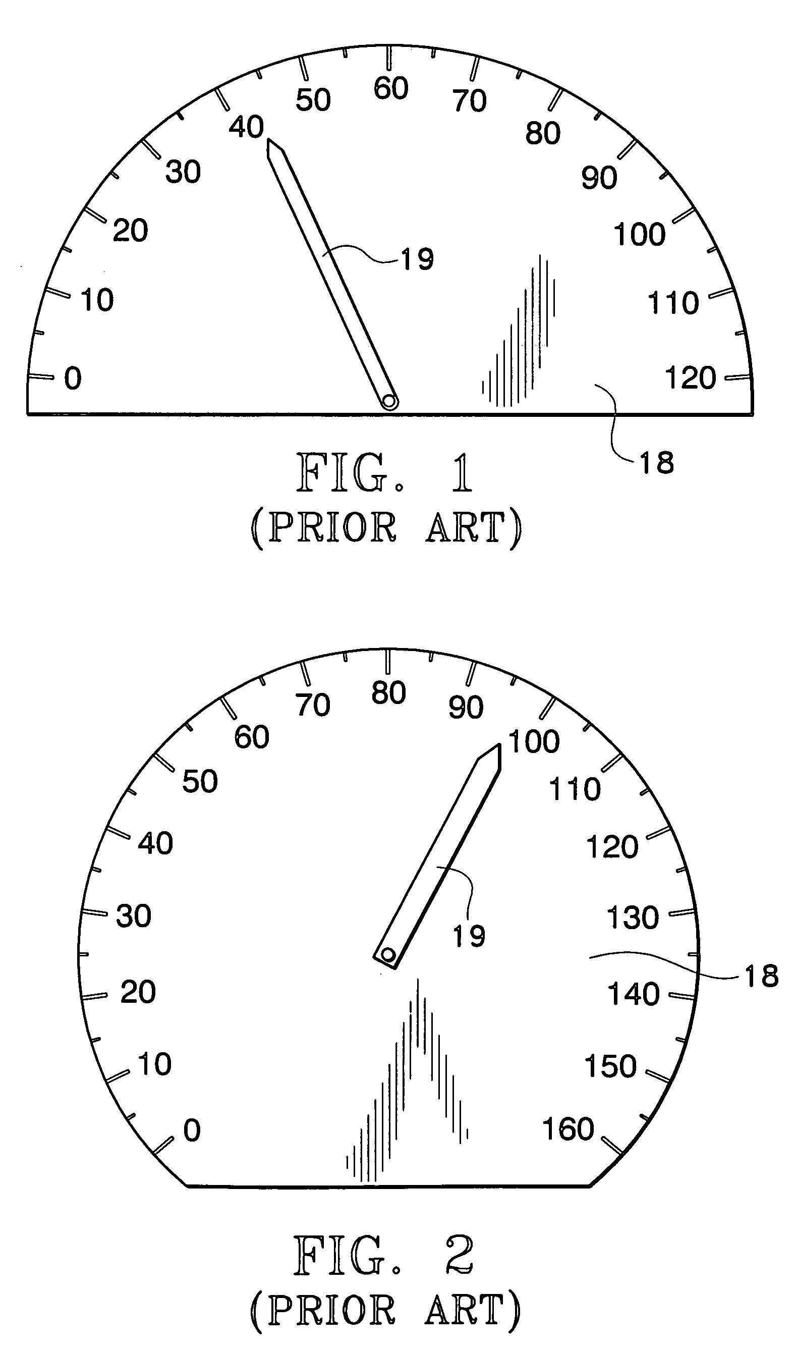
[0034]The most common speedometer face plates currently being utilized are in the form of a semi-circle FIG. 1 or a substantially full circle FIG. 2. The face plate 18 is often black with white numerals or white with black numerals and may be highlighted with a single color when the dashboard lights are turned on. A centrally located pointer 19 my also exhibit color when the dashboard lights are turned on.

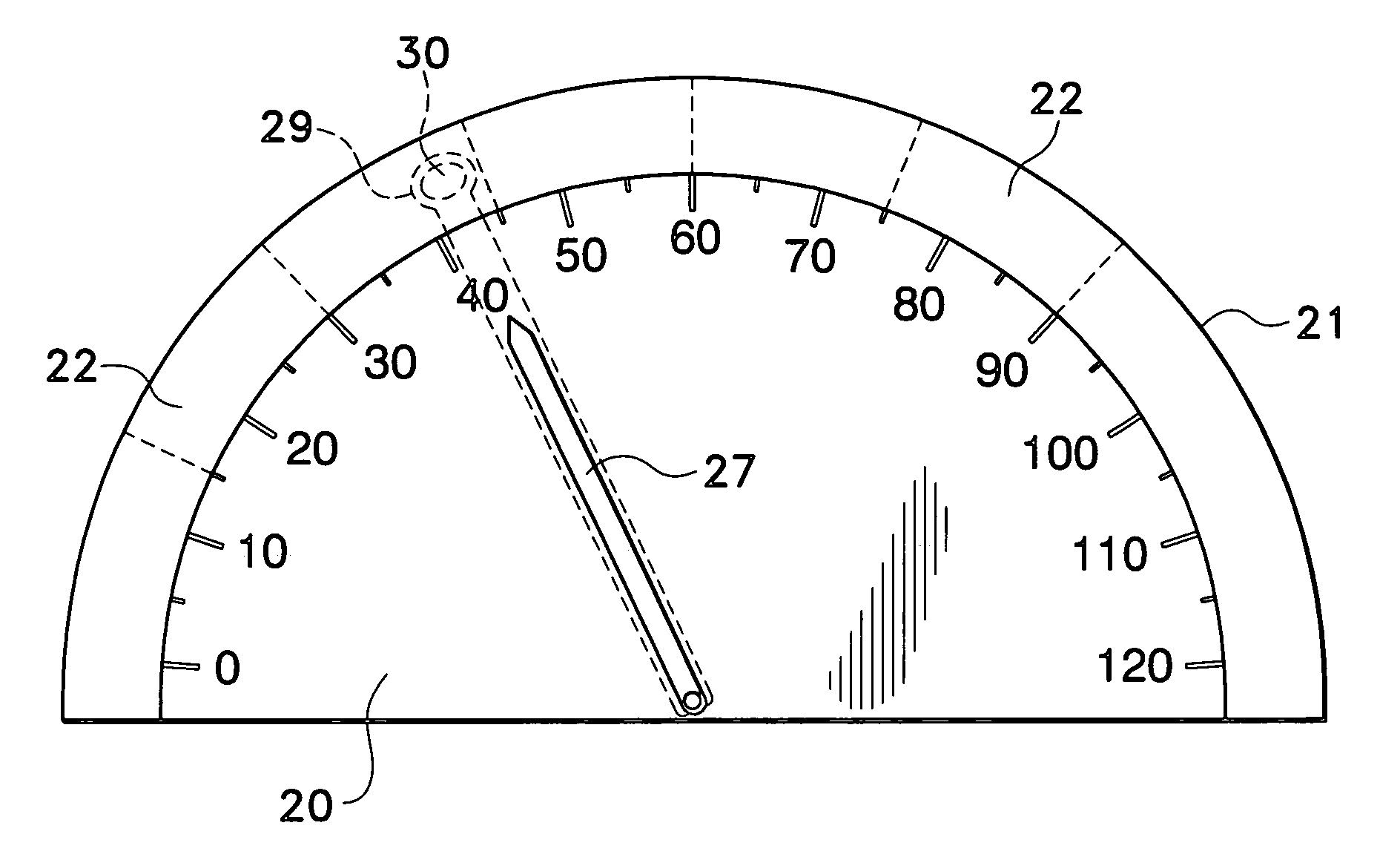
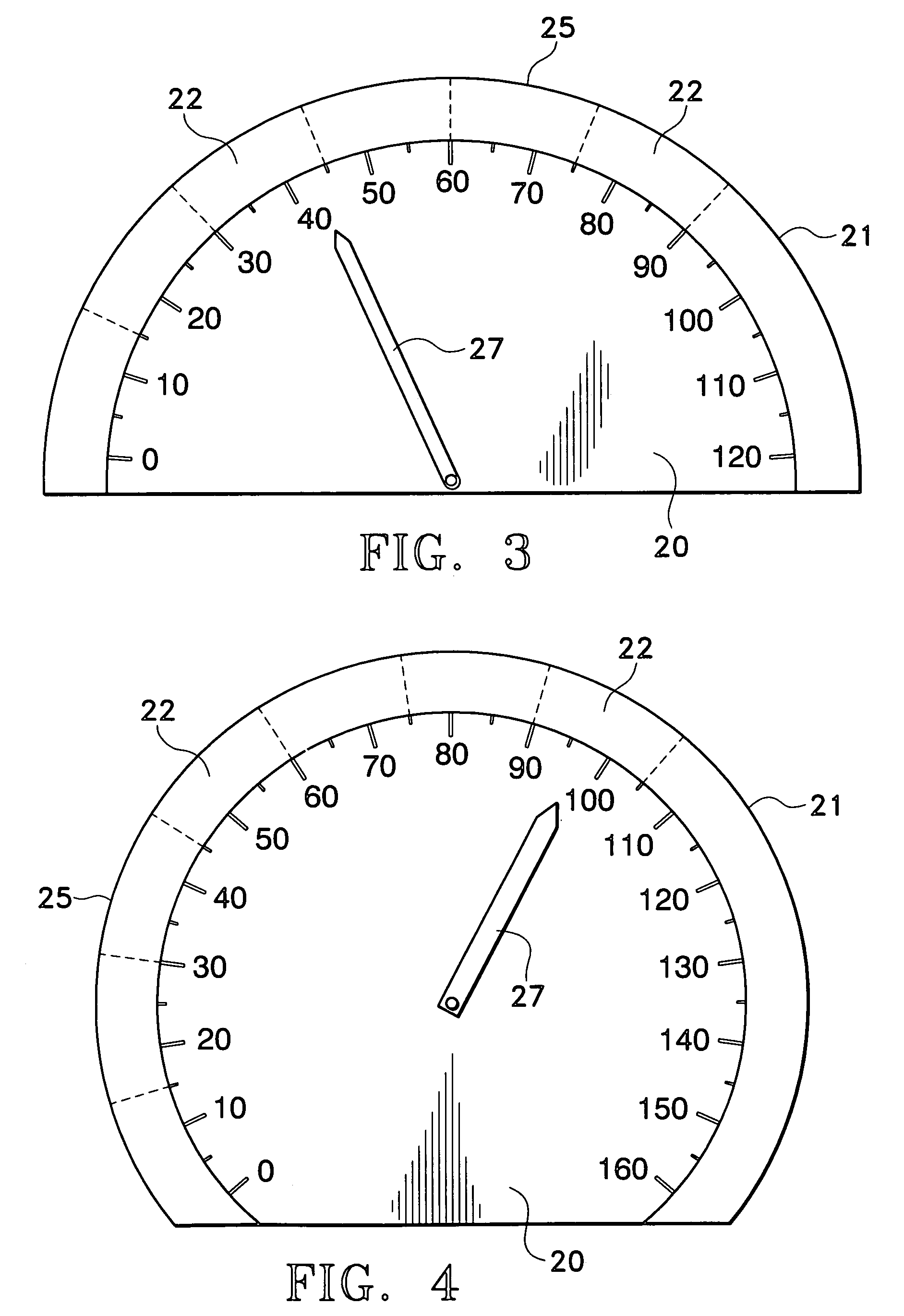
[0035]The speedometer of the present invention may have a similar face plate 20, with an obverse face 20A and a reverse face 20B seen in FIG. 6, but with the addition of a band or border 21 extending outward beyond the numerals as seen in FIGS. 3 and 4. This border 21 may be transparent or translucent and may be divided into a series of bounded areas or segments 22, each of a different color. The border 21 may be an extension of the face plate 20 and made up of the same material as the face plate 20 or the border may be made of another material that is affixed to the outer rim of t...


PUM


Abstract

A speedometer face plate assembly that incorporates a border of light transmitting segments above the speed indicating numerals is disclosed. Each of the segments is a different color. The colored segments are lighted from behind as the speed changes so that colored light is visible both peripherally and directly to the driver. Each color is associated with a specific speed increment so that once the driver becomes familiar with this speedometer face plate assembly, he or she will be aware of the speed traveled according to the color of the light and will not have to look directly at the speedometer as frequently as is currently necessary. In addition to the colored light transmitting border, there may also be a colored light transmitting section under the numerals or at another area on the speedometer face to further enhance the colored light effect. This speedometer face plate assembly contributes to increasing driving safety.

Description

FIELD OF THE INVENTION[0001]The instant invention relates to a speedometer face plate assembly with an illuminated color-varied border for peripheral view enhancement.BACKGROUND OF THE INVENTION[0002]In recent years motor vehicles have become increasingly more powerful and capable of traveling at higher and higher speeds. Speed limits have also been increasing and often vehicles travel considerably beyond posted speed limits. These powerful automobiles are so well built that high speeds can be attained without the driver being aware of just how fast he or she is traveling.[0003]The availability of cruise control devices have made it easier to stay within acceptable speed limits, but many drivers fail to take advantage of such devices making it necessary that the driver constantly look at the speedometer in order to maintain proper speed. The more often the driver's eyes are taken away from the road, the greater the chance of getting into a problem situation. A peripherally viewed sp...

Claims


Application Information

Patent Timeline
IPC IPC(8): G01D11/28
CPCG01D7/005G01D13/28G01D13/20G01D11/28B60K2350/2008B60K2370/188
Inventor RICHTER, MILTON
Owner RICHTER MILTON
Why Eureka
Try Eureka