Velocity profile impeller vane

a technology of impeller and profile, which is applied in the field of impellers, can solve the problems of wear on the side of the pump casing of the volute, and achieve the effects of reducing wear, reducing wear, and reducing wear

Active Publication Date: 2007-02-20
WEIR SLURRY GRP INC
View PDF7 Cites 1 Cited by
  • Summary
  • Abstract
  • Description
  • Claims
  • Application Information

AI Technical Summary

Benefits of technology

[0009]In accordance with the present invention, an impeller is provided having at least one vane that is particularly shaped at the outer terminal end thereof to produce flow velocities that are less deleterious to wear on the pump casing when processing slurries. The vane configurations of the present invention are adaptable for use in any rotodynamic pump which employs an impeller, but is described and illustrated herein in connection with use in a centrifugal slurry pump.
[0012]The convex-like outer terminal end of the vanes of the present invention generally produces a fluid velocity profile that reduces wear on the inside surface of the pump casing. The shape of the convex-like outer terminal end of the vanes may be particularly selected to specifically modify or determine the fluid velocity profile so that, given a particular type of slurry being processed, the wear on the pump casing can be controlled and reduced.

Problems solved by technology

It has been observed that the typical vane configuration having a straight outer edge, at or near the periphery of the shroud, produces a certain fluid velocity that leads to wear on the pump casing along the sides of the volute.

Method used


Image

  • Velocity profile impeller vane
  • Velocity profile impeller vane
  • Velocity profile impeller vane

Examples


first embodiment

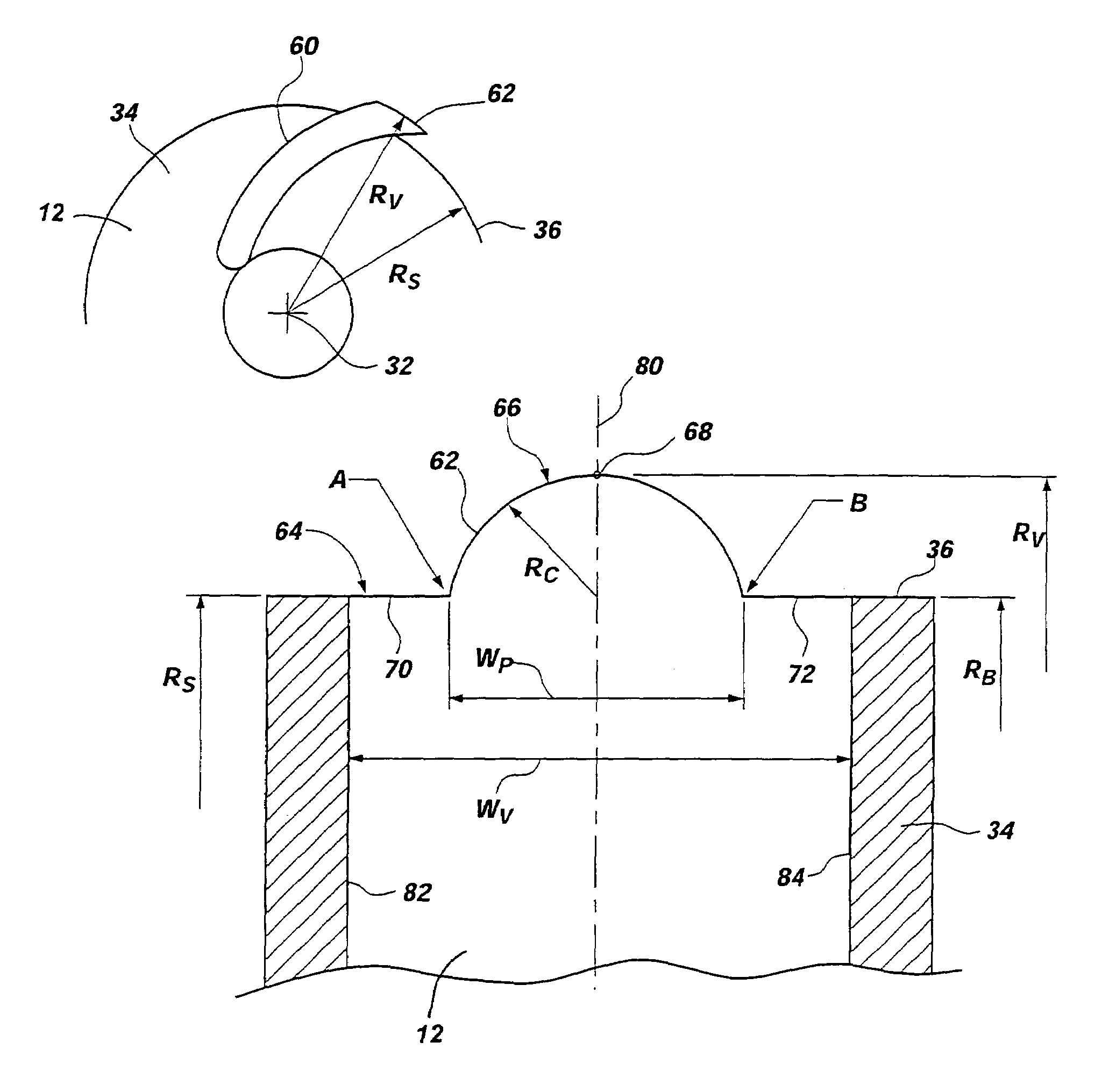
[0037]FIG. 8, however, illustrates the invention where the outer terminal end 64 of the vane 60 has an outwardly extending portion 66 that has a radius RV which is greater than the radius RS of the shroud 34. The outer edge 62 of the vane 60 is also configured with a portion 70, 72 on either side of the outwardly extending portion 66 that has a radius RB, which, in this embodiment, is equal to the radius RS of the shroud 34. Thus, the vane 60 has a width WV and the outwardly extending portion 66 has a width WP that is less than the width WV of the vane 60. It should be noted that in equally suitable alternative embodiments described more fully below, the width WP of the outwardly extending portion 66 may be equal to the width WV of the vane 60.

[0038]In the first embodiment of the present invention shown in FIG. 8, the outwardly extending portion 66 is generally arcuate in shape as measured from Point A to the terminus 68 of the outwardly extending portion 66 thence to Point B. Thus,...

fifth embodiment

[0042]FIGS. 8 and 9 depict alternative embodiments of the invention where the vane radius RV is a representational view in cross section of the present invention is greater than either the shroud radius RS and / or the base radius RB. FIGS. 10 and 11 illustrate other alternative embodiment of the invention. FIG. 10, for example, illustrates an alternative embodiment where the vane radius RV is slightly less than the shroud radius RS, and both the vane radius RV and shroud radius RS are greater than the base radius RB.

[0043]Yet another alternative is illustrated in FIG. 11 where the radius RV of the vane 60 and the radius RS of the shroud 34 are substantially equal, and both are greater than the base radius RB of the vane 60. Both of the embodiments illustrated in FIGS. 10 and 11 achieve a desired flow velocity that produces less wear on the volute of the pump casing. It should be noted that the convex-like outwardly extending portion 66 shown in FIGS. 10 and 11 is depicted as a hemisp...


PUM


Abstract

In accordance with the present invention, an impeller for use in a centrifugal pump has at least one vane the radially outer terminal end of which is configured to produce a flow velocity profile that controls and reduces the wear caused by slurry fluid being expelled from the impeller on the inner surface of the pump casing. The impeller vanes of the present invention are generally configured with a radially outwardly extending portion, as compared with the conventional straight or concave edge of an impeller vane. The outwardly extending portion may vary in shape, but is selected to produce a flow velocity profile that reduces wear in the pump casing.

Description

BACKGROUND OF THE INVENTION[0001]1. Field of the Invention[0002]This invention relates to pump impellers and specifically relates to an impeller having vanes particularly configured to selectively determine the velocity profile of the impeller to thereby selectively modify the wear of the pump casing when processing slurries.[0003]2. Description of Related Art[0004]Rotodynamic pumps are used in a variety of industries to process liquids and slurries. The type of fluid being processed dictates the type and configuration of the pump that is used in the particular application. That is, pumping clear liquid places less demand on pumps than does the processing of slurries, which contain an amount of solids or particulate matter that is abrasive and degrading to the internal structures of the pump.[0005]Therefore, pump designers and engineers must consider the type of fluid or slurry that is going to be processed and select or design an impeller and pump casing that is most suitable to th...

Claims


Application Information

Patent Timeline
Patent Type & Authority Patents(United States)
IPC IPC(8): F04D29/24B63H1/16F04D29/22
CPCF04D29/245F04D29/2288B63H1/16B63H1/10B64C11/00
Inventor WALKER, CRAIG I.ROUDNEV, ALEKSANDER S.
Owner WEIR SLURRY GRP INC
Why Eureka
Try Eureka