Eureka AIR delivers breakthrough ideas for toughest innovation challenges, trusted by R&D personnel around the world.

Intraocular lens for implantation in an eye and instrument and methods for insertion of such a lens

a technology for intraocular lenses and eye and instrument, which is applied in the field of intraocular lenses for implantation in eye and instrument and methods for insertion of such lenses, can solve the problems of difficult control of the position of the lens before insertion in the tube and after release from the tube, and the risk of damaging the anterior chamber and in particular the cornea, so as to reduce the risk of the lens touching and facilitate the handling of the lens. , the effect of improving the control of the lens orientation

Inactive Publication Date: 2007-02-20
OPHTEC
View PDF72 Cites 71 Cited by
  • Summary
  • Abstract
  • Description
  • Claims
  • Application Information

AI Technical Summary

Benefits of technology

[0015]The improved control over the orientation of the lens facilitates handling of the lens and immediately after release from the deformed condition in the passage, it reduces the risk of the lens touching sensitive tissue within the eye when released from the passage.

Problems solved by technology

A disadvantage of the rigid intraocular lens is that insertion of the lens requires a relatively large incision in the ocular tissue.
Release of the lens and the position of the lens before insertion in the tube and after release from the tube are difficult to control.
However, the semi-rigid anchor plate reduces compressibility of the lens and unfolding of the semi-rigid plate in the anterior chamber of the eye entails a risk of damaging eye tissue bounding the anterior chamber and in particular the cornea.
This entails that the stiffening element extends within the optic and accordingly reduces the effective optical area of the lens.
Moreover, reliable engagement of the forceps extending through a narrow lumen is difficult to ensure.
The lens has relatively slender haptics which can easily be damaged during passage through the lumen.
The emergence of the lens from the tube is difficult to control, in particular with respect to the velocity with which the lens regains its original shape and the orientation of the lens after emergence from the tube.
Furthermore, preparation of the lenses requires hydration or heating, deformation, and drying or cooling in deformed condition, which is relatively cumbersome.
Disadvantages of this treatment are that engaging the lens with the micro hooks is cumbersome and that a further incision in the eye is made for insertion of the second micro hook instrument that pulls the lens into the eye.
Furthermore, coordinated control of the two instruments inserted into the eye via different incisions is relatively difficult.

Method used


Image

  • Intraocular lens for implantation in an eye and instrument and methods for insertion of such a lens
  • Intraocular lens for implantation in an eye and instrument and methods for insertion of such a lens
  • Intraocular lens for implantation in an eye and instrument and methods for insertion of such a lens

Examples


Embodiment Construction

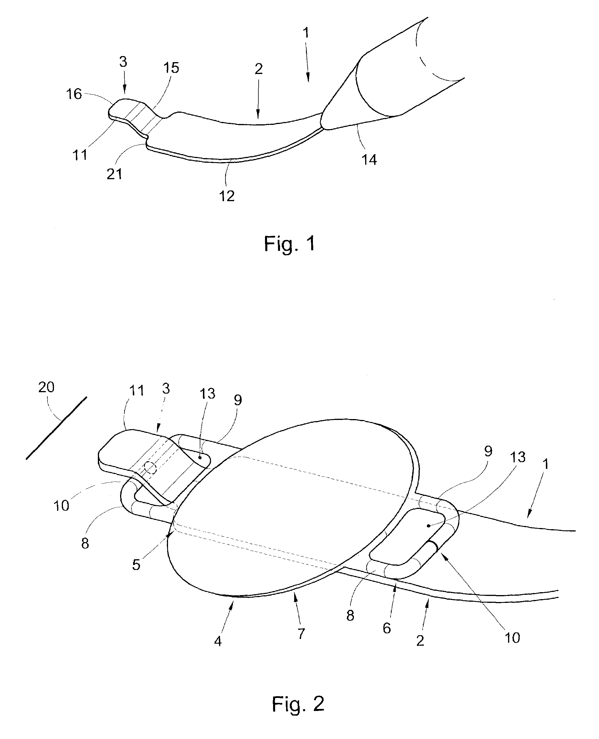
[0042]The invention is first described with reference to FIGS. 1 and 2, in which first examples of an instrument and a lens according to the invention are shown. The lens shown in FIG. 2 is also shown in FIG. 18.

[0043]The inserting instrument 1 shown in FIGS. 1 and 2 is for inserting an intraocular lens 4 into an eye via an incision 20 (schematically shown in FIG. 2) in the cornea. The instrument 1 has an elongate inserting member 2 projecting from a grip 14 and, at a distal end of the member 2, a hook 3 projecting transversally from the member 2. The lens 4 to be implanted using the instrument 1 has haptics 5, 6 radially projecting from opposite sides of an optical portion 7 of the lens 4. The optical portion 7 is deformable. The haptics 5, 6 are each formed by a pair of arms 8, 9 for clamping iris tissue between surfaces of the arms 8, 9 facing each other in a clamping area 10 and are arranged for supporting the optical portion 7 in a position parallel to and against an anterior i...


PUM


Abstract

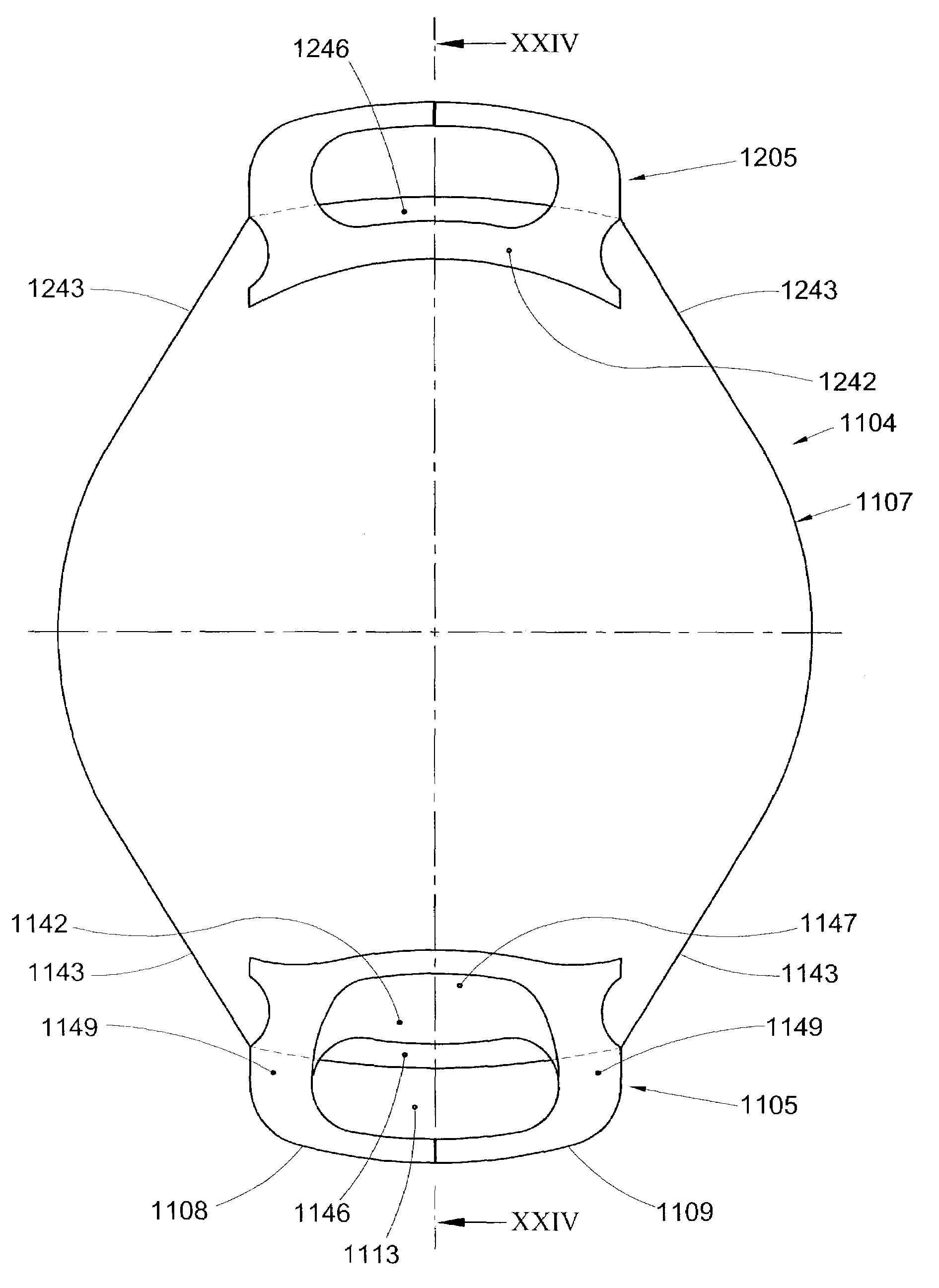
An intraocular lens includes an optical portion (7; 607; 907; 1107) of a transparent, deformable material, at least one haptic (5, 6; 205, 206; 405, 406, 706; 806; 905; 1005; 1105; 1205) radially projecting from the optical portion for supporting the optical portion in a position parallel to and against an anterior iris surface plane (936; 1136), and at least one aperture (13; 213; 713; 913; 1013; 1113) bounded by the haptic. At least a stiff portion of the haptic has a higher stiffness against bending about an axis in the radial direction than the optical portion. Furthermore, the stiff portion has a width (a) measured parallel to the plane and perpendicular to the radial direction, which is smaller than the size (b) of the optical portion in the direction of the width. An instrument and methods for preparing and carrying out insertion of such a lens are also described.

Description

[0001]This application claims the benefit of U.S. Provisional Application No. 60 / 364,514, filed Mar. 15, 2002.FIELD AND BACKGROUND OF THE INVENTION[0002]The invention relates to a lens, to an instrument for inserting an intraocular lens into an eye, to a method for preparing an intraocular lens for insertion into an eye and to a method for inserting an intraocular lens into an eye, including such a preparatory method. Such a lens, such an instrument and such methods are known from U.S. Pat. No. 4,573,998.[0003]Implantation of an intraocular lens after surgical removal of the opaque lens, a structure having a thickness of about 5 millimeters and diameter of about 9 millimeters, from the eye of a cataract patient is one of the most common forms of eye surgery. The lens is usually implanted in the anterior chamber of the eye (in front of the iris) or in the posterior chamber of the eye (behind the iris) in the capsular bag or in the sulcus.[0004]Another indication for the prescription ...

Claims


Application Information

Patent Timeline
Patent Type & Authority Patents(United States)
IPC IPC(8): A61F2/14A61F2/16
CPCA61F2/1662
Inventor WORST, JAN GERBEN FRANSSIMON, HARRY FRANCISCUSAPONNO, MARTINUS
Owner OPHTEC
Why Eureka
Eureka Blog
Learn More