Simple partial discharge detector for power equipment using acoustic emission technique

a technology of acoustic emission and a detector, which is applied in the direction of instruments, measuring devices, testing dielectric strength, etc., can solve the problems of power failure and disruption of plants, high cost of computer treatment at the post-end of couple capacitors, and even higher cost of computer treatment at the post-end, so as to reduce the load of the cpu in the host. , the effect of costing much less

Inactive Publication Date: 2007-02-20
UNELECTRA INT CORP +3
View PDF2 Cites 12 Cited by
  • Summary
  • Abstract
  • Description
  • Claims
  • Application Information

AI Technical Summary

Benefits of technology

[0022]The detector of the present invention needs no host, costs much low, and real-time inspection can be achieved. If central inspection is necessary, the mic...

Problems solved by technology

When the insulated material worsens, the transformers may be damaged or even explode, which will result in power failure and disrupture of plants.
In this method, pulse current of partial discharge in the detection circuit can be detected, which is easily quantified and highly sensitive.
As frequencies of the signals are generally more than 5 MHz, cost for computer treatment at post-end of the couple capacitor is quite high.
However, frequencies of such current signals are as high as several MHz˜tens of MHz, and thus cost for computer treatment at the post-end is even higher.
For common industries, grounding is a complicated issue as the partial discharge signals are easily interfered and covered by other signals.
To solve such problems, a better filter or a more complicated filtering program is required and thus cost will be much higher.
However, when the source of partial discharge is caused by media inside the equipment, for example, insulated oil in an oil-immersed transformer, resin in the cast resin transformer and SF6 in GIS; the acoustic waves of discharge are hardly transmitted to t...

Method used


Image

  • Simple partial discharge detector for power equipment using acoustic emission technique
  • Simple partial discharge detector for power equipment using acoustic emission technique
  • Simple partial discharge detector for power equipment using acoustic emission technique

Examples


Embodiment Construction

[0026]The present invention will be further illustrated with the preferred embodiments and the related drawings.

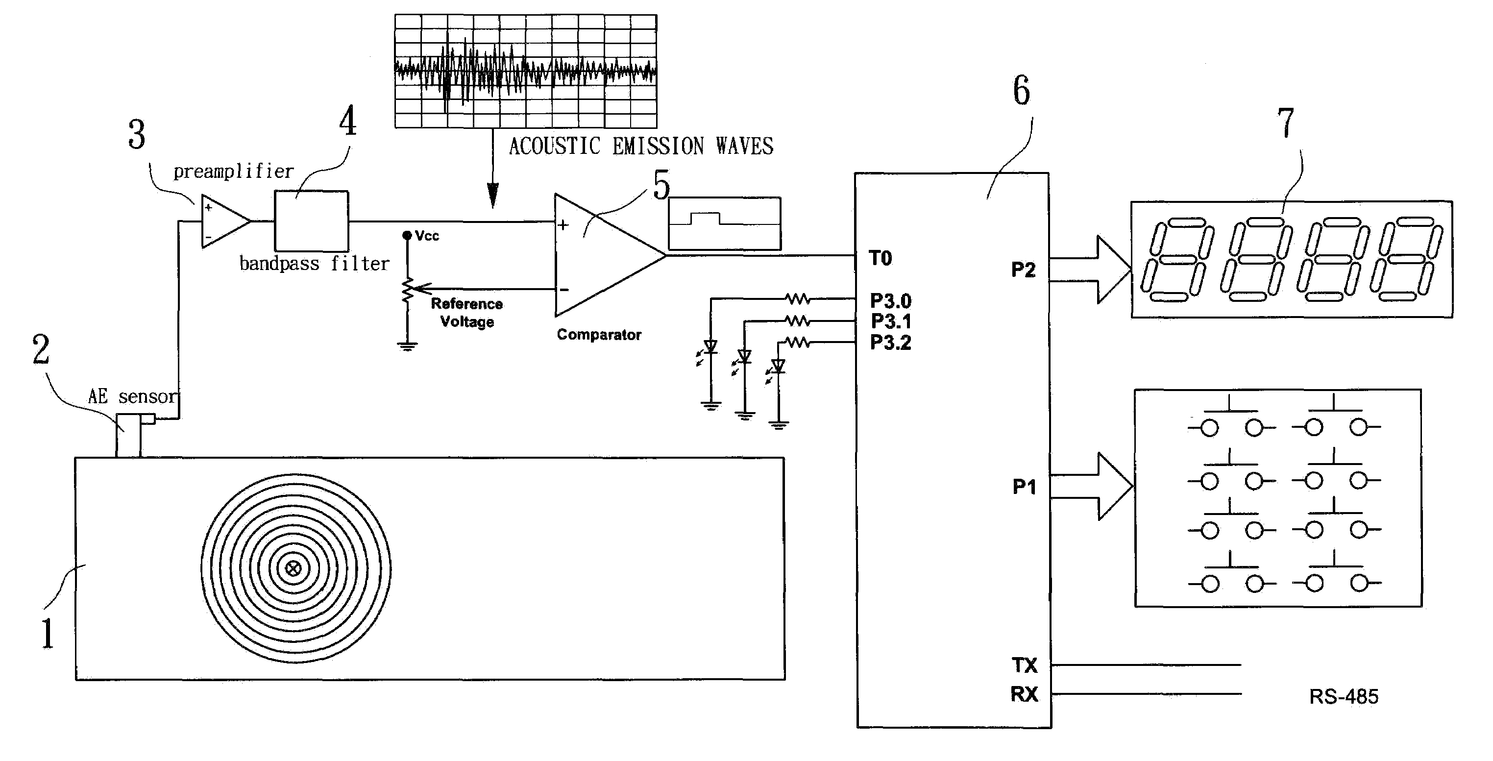
[0027]Please refer to FIG. 3, which shows a simple detector for partial discharge with an acoustic emission technique in accordance with the present invention. On a power equipment (1), an acoustic emission sensor (2) is set to capture acoustic emission signals generated by the power equipment (1). A preamplifier (3) is connected to an output of the acoustic emission sensor (2) to amplify the acoustic emission signal. A bandpass filter (4) is connected to the preamplifier (3) to filter the acoustic emission signals having high and low frequencies. A comparator (5) is set on the output of the bandpass filter (4) to transform the acoustic emission signals having proper frequencies into square-wave signals which are then transmitted to a microprocessor (6). The microprocessor (6) comprises a counter inside to count times for partial discharge by second. An output of the count...


PUM


Abstract

The present invention relates to a simple detector for partial discharge with the acoustic emission technique, which provides essentially with an acoustic emission sensor being set on a power equipment. Still, the output of the acoustic emission sensor is connected with a preamplifier and a bandpass filter in turn and the output of the bandpass fitted up with a comparator. The signals of square waves generated by the comparator can be transmitted to a microprocessor as concurrently as a counter in the microprocessor can be used to count up times for partial discharge by seconds; then, the resulted times can be displayed. Consequently, it is convenient to determine whether the power equipment is necessarily maintained by means of counting up times for partial discharge.

Description

BACKGROUND OF THE INVENTION[0001]1. Field of the Invention[0002]The present invention relates to a simple discharge detector for a power equipment using the acoustic emission technique, in which acoustic emission signals are particularly transformed into square-wave signals by a comparator and then transmitted to a microprocessor, and a counter inside the microprocessor is provided to count times of partial discharge so as to determine whether the power equipment needs to be maintained or not.[0003]2. Related Prior Arts[0004]To promote efficiency of electricity transmission, voltage during transmission is greatly increased, and thus insulated material used for transformers and gas insulated switchgears (GIS) in plants are necessarily capable of standing high potential. When the insulated material worsens, the transformers may be damaged or even explode, which will result in power failure and disrupture of plants. Therefore, it's more and more important to maintain and detect power e...

Claims


Application Information

Patent Timeline
IPC IPC(8): H01H9/50
CPCH01H9/50
Inventor CHEN, JIANN-FUHTAI, CHEN-CHILIANG, TSORNG-JUUSU, CHING-CHAUYI, CHING-SHUNCHEN, CHIEN-YI
Owner UNELECTRA INT CORP
Why Eureka
Try Eureka