Redundancy structures and methods in a programmable logic device

a logic device and redundancy structure technology, applied in logic circuits, pulse techniques, reliability increasing modifications, etc., can solve the problems of limited reparability of parts, damage to adjacent lines in track groups, etc., to achieve maximum reparability, limit the chance of damage, and reduce the effect of damag

Inactive Publication Date: 2007-02-20
ALTERA CORP
View PDF22 Cites 61 Cited by
  • Summary
  • Abstract
  • Description
  • Claims
  • Application Information

AI Technical Summary

Benefits of technology

[0008]In one respect, if routing redundancy in a row-shifting redundancy scheme requires driving the same physical line from a different row depending on whether redundancy is engaged, a single vertical line may require an extra driver for redundancy in a redundant mode row below a normal mode driving row. However, in the context of vertical lines that are staggered, it is possible to selectively utilize one vertical line or another vertical line in order to effectively shift the row (or rows) from which a particular signal would otherwise be driven and received. Such selective use of a first or second vertical line for signal routing has the potential to help reduce the need for additional drivers in a row-shifting redundancy scheme.
[0010]In another and different respect, in a staggered segmented routing architecture, it is possible that a defect will damage adjacent lines in a track group. If staggered lines are grouped such that lines having different drive points are adjacent, the reparability of the part may be limited. Thus, there is a need for a grouping scheme in a staggered segmented routing architecture that better maximizes reparability.
[0011]In another and different respect, opportunities for repair may be restrained if spare row locations must be pre-designated before the locations of defective rows are known. Thus, there is a potential benefit in being able to define spare row locations after defective row locations are known.
[0012]In one aspect, some embodiments of the present invention implement a redundancy scheme to selectively route from first or second vertical lines. In another aspect, some embodiments of the present invention implement a redundancy scheme by programming configuration elements that control inputs of a routing input mux coupled to vertical lines. In some embodiments, the configuration elements are treated as pairs; also, mux inputs and stages are organized so that the configuration element pairs are in a same frame of configuration elements. In other embodiments, the pairs of configuration elements are also consecutive. In yet other embodiments, the configuration elements are treated separately and two configuration elements controlling relevant mux inputs may be non-consecutive and in different frames of configuration elements. In another aspect, various embodiments of the present invention may employ a variety of divisions between on-chip hardware and off-chip software to implement a redundancy scheme. In another aspect, some embodiments include vertical lines having both upstream and downstream connections relative to a driver row. In yet another aspect, some embodiments of the present invention provide proximate grouping of vertical lines driven from the same row to maximize reparability of multi-line defects. In yet another aspect, some embodiments of the invention may allow for “on-the-fly” definition of spare row location to further maximize repair.

Problems solved by technology

In another and different respect, in a staggered segmented routing architecture, it is possible that a defect will damage adjacent lines in a track group.
If staggered lines are grouped such that lines having different drive points are adjacent, the reparability of the part may be limited.

Method used


Image

  • Redundancy structures and methods in a programmable logic device
  • Redundancy structures and methods in a programmable logic device
  • Redundancy structures and methods in a programmable logic device

Examples


Embodiment Construction

[0029]The following description is presented to enable any person skilled in the art to make and use the invention, and is provided in the context of particular applications and their requirements. Various modifications to the exemplary embodiments will be readily apparent to those skilled in the art, and the generic principles defined herein may be applied to other embodiments and applications without departing from the spirit and scope of the invention. Thus, the present invention is not intended to be limited to the embodiments shown, but is to be accorded the widest scope consistent with the principles and features disclosed herein.

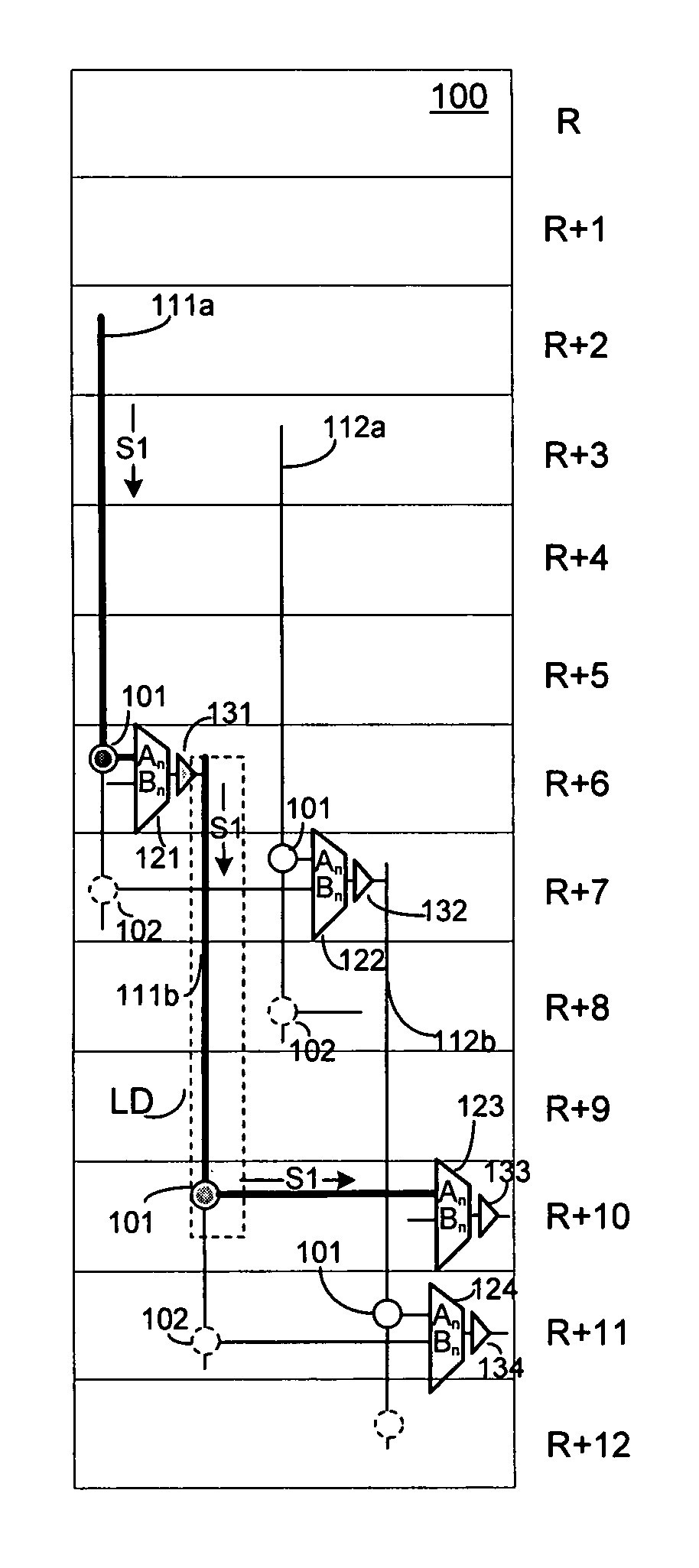
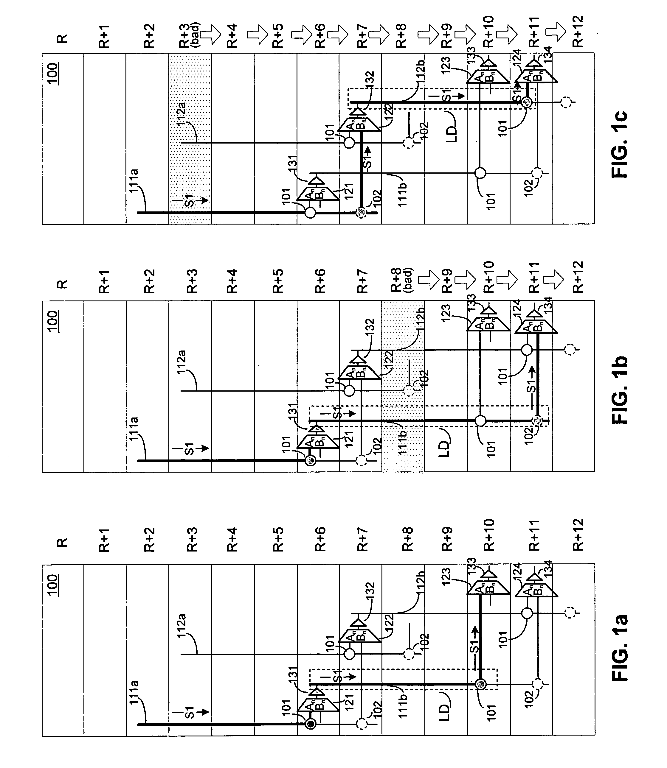
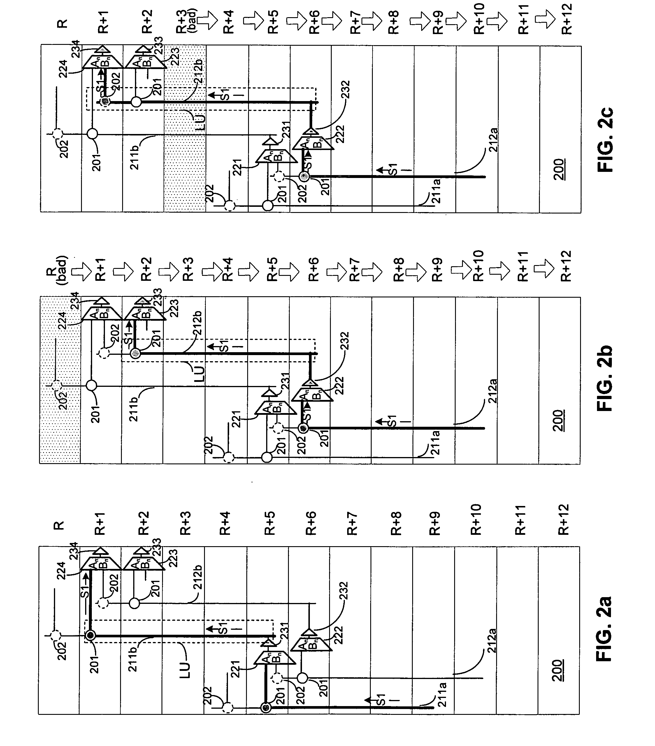
[0030]FIGS. 1a–1c illustrate routing from downstream vertical lines for selected rows in a portion 100 of a PLD operating in normal (FIG. 1a) and redundant (FIGS. 1b–1c) modes in accordance with an embodiment of the present invention. “Downstream” simply refers to the fact connections from these lines are located downstream from the line driver where ...


PUM


Abstract

An embodiment of the present invention provides a programmable logic device (“PLD”) including a redundancy architecture adapted to selective route signals via first or second staggered vertical lines. Other embodiments provide configuration logic and programs for determining routing selections. Other embodiments provide proximate grouping of vertical lines driven from a same row. Other embodiments provide definition of spare row locations once defective row locations are known.

Description

BACKGROUND OF THE INVENTION[0001]1. Field of the Invention[0002]The present invention relates to programmable logic devices having redundant circuitry.[0003]2. Description of Related Art[0004]Programmable logic devices (“PLDs”) (also sometimes referred to as CPLDs, PALs, PLAs, FPLAs, EPLDs, EEPLDs, LCAs, FPGAs, or by other names), are well-known integrated circuits that provide the advantages of fixed integrated circuits with the flexibility of custom integrated circuits. Such devices are well known in the art and typically provide an “off the shelf” device having at least a portion that can be programmed to meet a user's specific needs. Application specific integrated circuits (“ASICs”) have traditionally been fixed integrated circuits, however, it is possible to provide an ASIC that has a portion or portions that are programmable; thus, it is possible for an integrated circuit device to have qualities of both an ASIC and a PLD. The term PLD as used herein will be considered broad ...

Claims


Application Information

Patent Timeline
Patent Type & Authority Patents(United States)
IPC IPC(8): H03K19/003H03K19/177
CPCH03K19/17764H03K19/17736
Inventor CHAN, MICHAELLEVENTIS, PAULLEWIS, DAVIDZAVERI, KETANYI, HYUN MOLANE, CHRIS
Owner ALTERA CORP
Why Eureka
Try Eureka