Receiver having full signal path differential offset cancellation capabilities

a technology of differential offset and receiver, which is applied in the field of high-speed serial communication/data transfer, can solve the problems of inability to cancel the differential offset, the signal amplitude and slew rate is much reduced, and the signal degradation, due to the differential offset, becomes prohibitiv

Inactive Publication Date: 2007-02-20
IBM CORP
View PDF5 Cites 30 Cited by
  • Summary
  • Abstract
  • Description
  • Claims
  • Application Information

AI Technical Summary

Benefits of technology

[0008]It is therefore a primary object of the present invention to provide an improved receiver having full signal path differential offset compensation capabilities that totally eliminates the differential offset a driver and a receiver.
[0010]It is another object of the present invention to provide an improved receiver having full signal path differential offset compensation capabilities that cancels more than 90% of the differential offset magnitude at the receiver level.

Problems solved by technology

With the increasing frequency of signals used in modern communication links, unwanted effects such as cross talk, ringing, reflection, ISI, offset, clock jitter and the like, occur due to the distributed nature of the media which transports these signals.
As the signal frequency increases and / or the distance to communicate, and due to the limited bandwidth of the transporting media (or cost limitation), the signal amplitude and slew rate is much reduced so that the signal degradation, due to the differential offset, becomes prohibitive.
Data jitter and / or phase error (skew) can significantly reduce the useful sampling window.
This basically reduces the following sampling circuit tolerance to the jitter and could increase the bit error rate (BER).
Other applications such as high speed point to point back plane communications will suffer from the same problem, the differential offset becomes prohibitive due to the media attenuation at speed above the GHz.
On the other hand, the jitter and ISI have also a detrimental effect on the closure of the signal eye.
For high speed data transfers, this ISI can substantially decrease the capacity of the receivers to tolerate the random data jitter.
Keeping in mind that the specification related to ISI (intersymbol interference) is very aggressive, such receivers could not be operative with this standard.

Method used


Image

  • Receiver having full signal path differential offset cancellation capabilities
  • Receiver having full signal path differential offset cancellation capabilities
  • Receiver having full signal path differential offset cancellation capabilities

Examples


Embodiment Construction

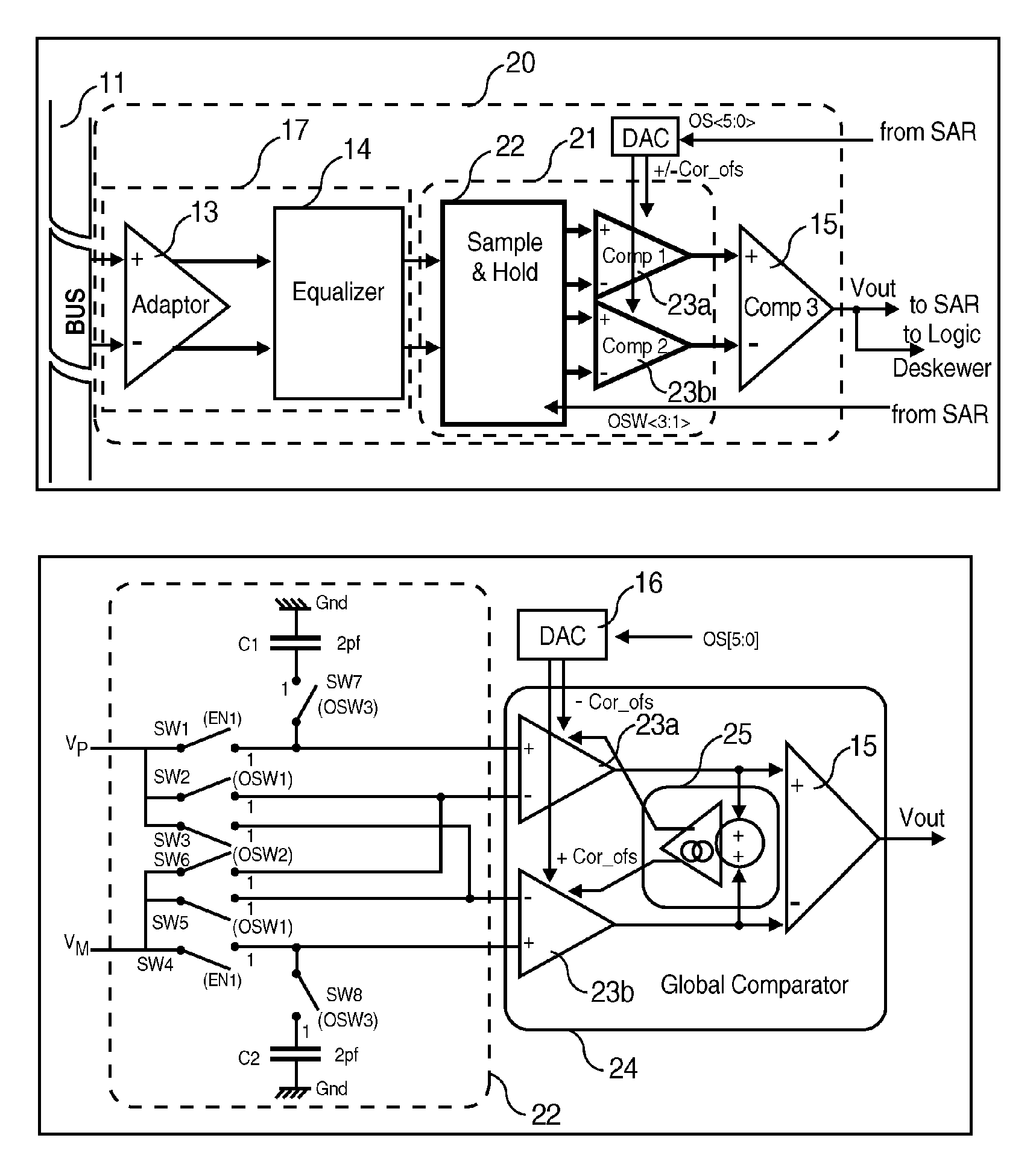
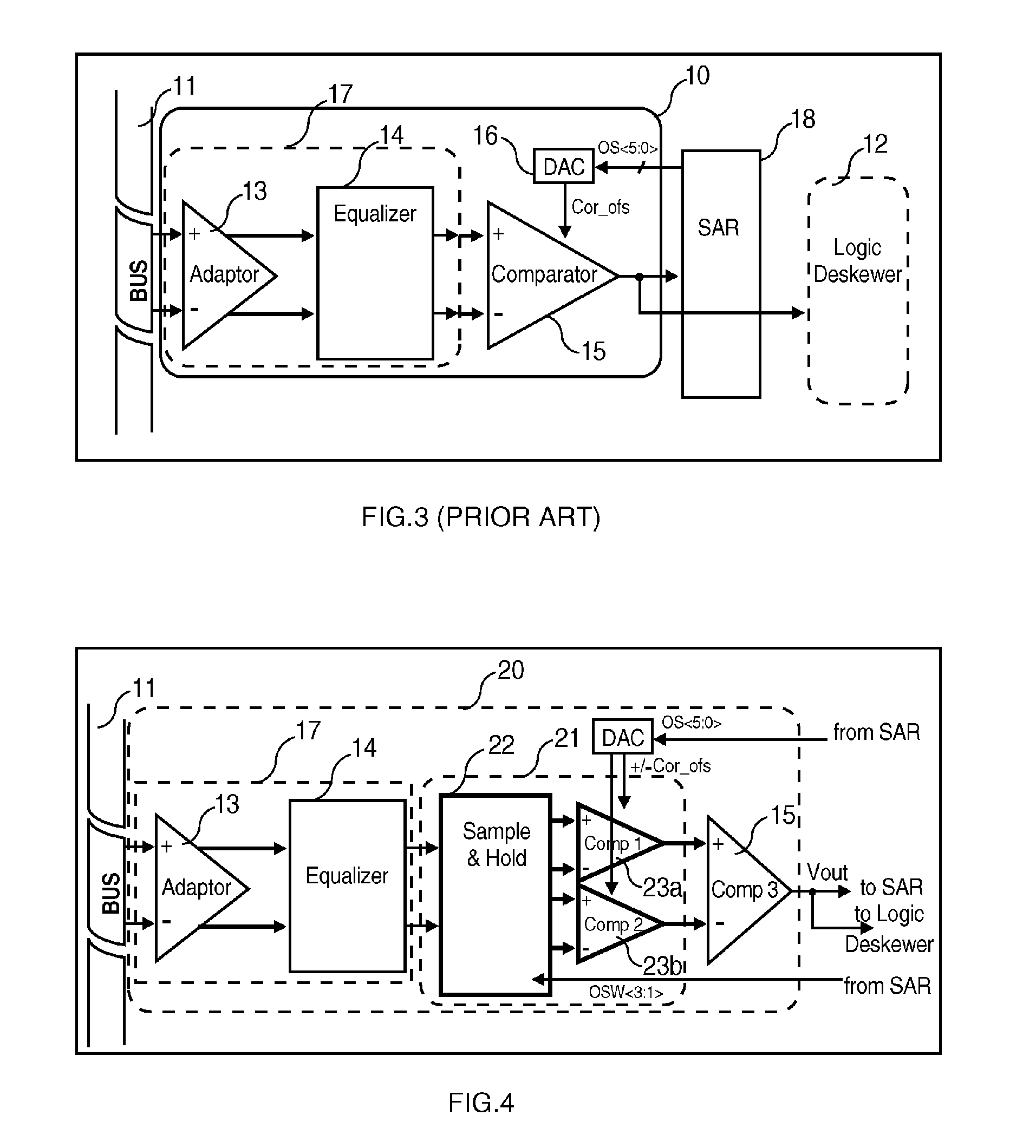
[0029]FIG. 4 shows the schematic diagram of the improved receiver referenced 20 of the present invention placed between bus 11 (which now can be a SCSI-pi5 bus) and the logic deskewer block 12 as an interface (like reference numerals are used through the several drawings to designate identical parts). In the SCSI-pi5 application, there are up to 27 of such improved receiver 20. Now turning to FIG. 4, the improved receiver 20 differentiates of the conventional receiver 10 by the addition of block 21 between the outputs of equalizer 14 and the inputs of comparator 15. This block consists of a sample and hold circuit 22 that drives a pair of comparators 23a and 23b. The comparators 23a and 23b are respectively controlled by signal Cor_ofs and its inverted (complemented) value −Cor_ofs generated by DAC 16 (the compensation value is still determined and stored as binary digits in the SAR 18 as standard). These new elements are shown in bold lines in FIG. 4. Comparators 23a, 23b and 15 fo...


PUM


Abstract

There is described an improved receiver which first comprises an analog input amplifier a sample and hold differential circuit and two stages of differential comparators that are connected in series, wherein the first stage consists of two comparators and the second stage of one comparator. By properly activating the switches with signals generated by a dedicated control logic, the input differential signal is sampled in the sample and hold circuit to generate first and second differential signals. The first differential signal holds a first state and the second differential signal propagates the second state. As result, the signal output by the second comparator stage reflects the differential offset minus the offset compensation.

Description

FIELD OF THE INVENTION[0001]The present invention relates to high speed serial communications / data transfers between integrated circuits or systems and more particularly to an improved receiver provided with an innovative serial link offset cancellation circuit that compensates the full signal path to eliminate the totality of the differential offset from the driver to the receiver whatever data are encoded or not. The present invention also encompasses a method for compensating the full signal path differential offset between the driver and the receiver, including the one caused by the transporting media and the adaptation, whatever data are encoded or not.BACKGROUND OF THE INVENTION[0002]With the increasing frequency of signals used in modern communication links, unwanted effects such as cross talk, ringing, reflection, ISI, offset, clock jitter and the like, occur due to the distributed nature of the media which transports these signals. A major contributor in DC coupled lines is...

Claims


Application Information

Patent Timeline
Patent Type & Authority Patents(United States)
IPC IPC(8): H03L5/00G11C27/02H03F1/02H03F3/45
CPCH03F3/45775G11C27/026
Inventor GABILLARD, BERTRANDHAUVILLER, PHILIPPEMALTERE, ALEXANDRERO, CHRISTOPHER
Owner IBM CORP
Why Eureka
Try Eureka