Broadband internal antenna

a broadband, internal antenna technology, applied in the direction of resonant antennas, elongated active elements, radiating element structural forms, etc., can solve the problems of deteriorating the competitive power of recent mobile communication terminals, difficult to apply to actual mobile terminals, and high unit cost of these devices

Inactive Publication Date: 2007-02-20
SAMSUNG ELECTRO MECHANICS CO LTD
View PDF17 Cites 48 Cited by
  • Summary
  • Abstract
  • Description
  • Claims
  • Application Information

AI Technical Summary

Benefits of technology

[0015]Accordingly, the present invention has been made keeping in mind the above problems occurring in the prior art, and an object of the present invention is to provide an antenna, which can be mounted in a mobile communication terminal, can be miniaturized, and can be easily implemented.
[0016]Another object of the present invention is to provide the internal antenna of a mobile communication terminal, which has excellent broadband characteristics.

Problems solved by technology

However, the conventional internal dual band antenna is constructed in such a way that all the radiation parts are formed on a single plane, so that the size thereof is large and the unit cost thereof is high, thus deteriorating the competitive power of recent mobile communication terminals.
However, the conventional ceramic chip antenna 30 is problematic in that it is sensitive to external factors because it has a narrow bandwidth, and it is difficult to be applied to an actual mobile terminal because the manufacturing cost thereof is high.

Method used


Image

  • Broadband internal antenna
  • Broadband internal antenna
  • Broadband internal antenna

Examples


Embodiment Construction

[0039]Preferred embodiments of the present invention are described with reference to the attached drawings below. Reference now should be made to the drawings, in which the same reference numerals are used throughout the different drawings to designate the same or similar components. In the following description of the present invention, detailed descriptions may be omitted if it is determined that the detailed descriptions of related well-known functions and construction may make the gist of the present invention unclear.

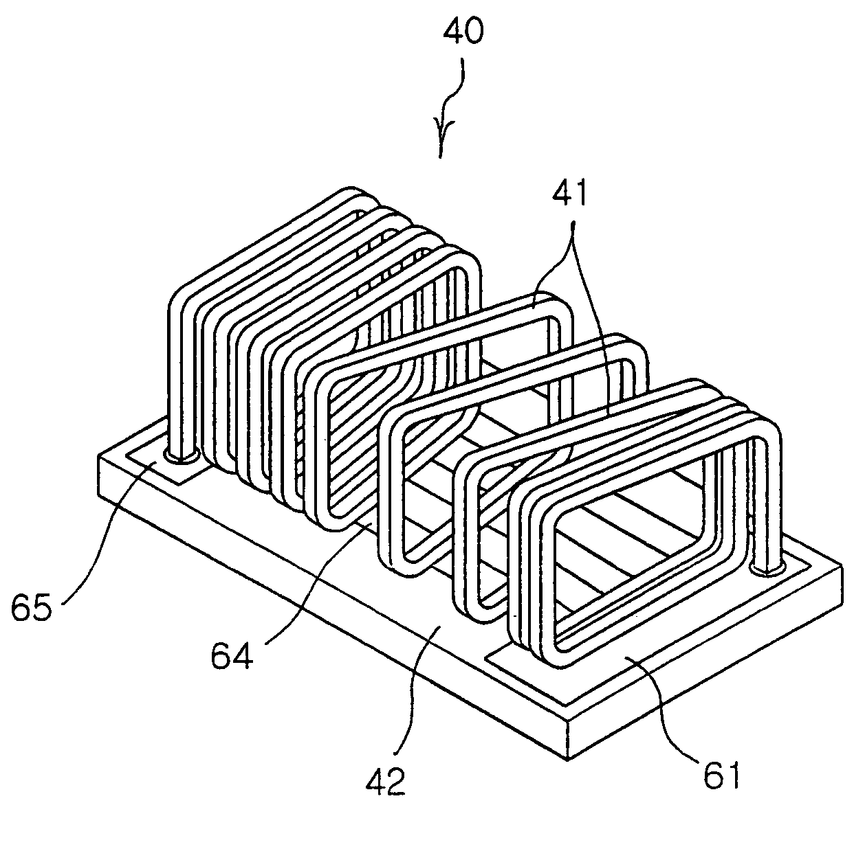
[0040]FIG. 4 is a view showing the basic construction of a broadband internal antenna 40 according to an embodiment of the present invention.

[0041]Referring to FIG. 4, the broadband internal antenna 40 according to the embodiment of the present invention includes a first radiator 41 and a second radiator 42.

[0042]The first radiator 41 has a structure in which one or more coils having different pitch intervals are connected in series. The first radiator 41 can form ...


PUM


Abstract

A broadband internal antenna includes a first radiator having a radiation part with one or more coils having different pitch intervals connected in series to each other, and a second radiator having at least one conductive strip line arranged parallel to a longitudinal direction of the first radiator. The antenna further includes a connection part to which an end of the at least one conductive strip line is connected, to which a first end of the first radiator is attached and in which a part for supplying current to the antenna and a part for grounding the antenna are formed, and an attachment pad to which a second end of the first radiator is attached and from which current is drawn. Current flowing through the first radiator and current flowing through the strip lines form current paths in different directions to set a certain broadband using mutual Electromagnetic (EM) coupling.

Description

RELATED APPLICATION[0001]The present application is based on, and claims priority from Korean Application Number 2004-81860, filed Oct. 13, 2004, the disclosure of which is incorporated by reference herein its entirety.BACKGROUND OF THE INVENTION[0002]1. Field of the Invention[0003]The present invention relates generally to an antenna provided in a mobile communication terminal to transmit and receive radio signals and, more particularly, to a broadband internal antenna provided in a mobile communication terminal to process broadband signals.[0004]2. Description of the Related Art[0005]Currently, mobile communication terminals are required to provide various services as well as be miniaturized and lightweight. To meet such requirements, internal circuits and components adopted in the mobile communication terminals trend not only toward multi-functionality but also toward miniaturization. Such a trend is also applied to an antenna, which is one of the main components of a mobile comm...

Claims


Application Information

Patent Timeline
Patent Type & Authority Patents(United States)
IPC IPC(8): H01Q21/00H01Q1/36H01Q5/10H01Q5/321H01Q9/04H01Q9/40H01Q9/42H01Q21/30
CPCH01Q1/362H01Q9/0421H01Q5/371H01Q5/357H01Q21/30H01Q1/243H01Q5/00H01Q1/24
Inventor OH, SAE WONKIM, CHUL HOKIM, HYUN HAKKIM, TAE SUNGKIM, YOUNG DEGDO, GI TAE
Owner SAMSUNG ELECTRO MECHANICS CO LTD
Why Eureka
Try Eureka