Light condensing filter

a filter and light technology, applied in the field of light condensing filters, can solve the problems of loss of optical film or liquid crystal layer, uneven light, etc., and achieve the effects of enhancing a light condensing effect, high flatness, and further enhancing the light condensing

Inactive Publication Date: 2007-02-20
FUJIFILM HLDG CORP +1
View PDF19 Cites 15 Cited by
  • Summary
  • Abstract
  • Description
  • Claims
  • Application Information

AI Technical Summary

Benefits of technology

[0014]An object of the invention is to provide a light condensing filter which can suppress moire in a liquid crystal display device with enhancing a light condensing effect.
[0015]Furthermore, the present invention has another object to provide a light condensing filter having high flatness which can suppress moiré in a liquid crystal display device.

Problems solved by technology

Accordingly, when optical film such as a diffusion plate or the like or a liquid crystal layer is disposed on the plural prisms 1 of this prism sheet, flatness of the optical film or the liquid crystal layer is lost, and thus there is a problem that unevenness of light occurs or the like.

Method used


Image

  • Light condensing filter
  • Light condensing filter
  • Light condensing filter

Examples


first embodiment

(First Embodiment)

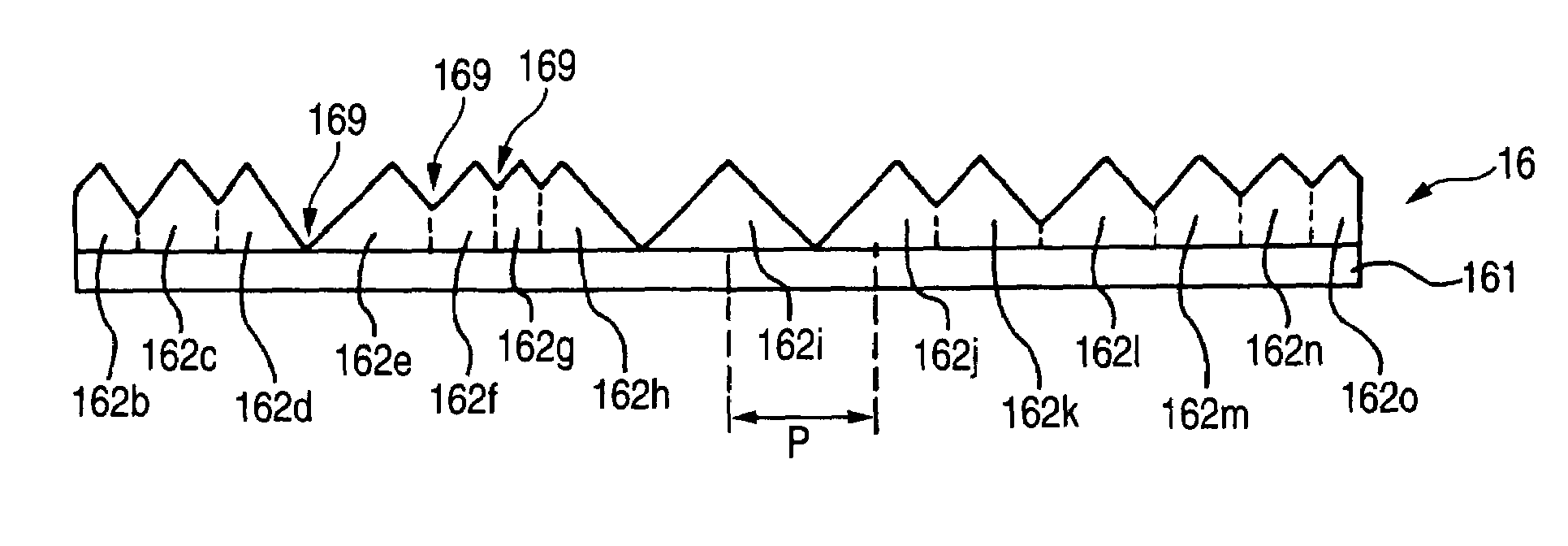
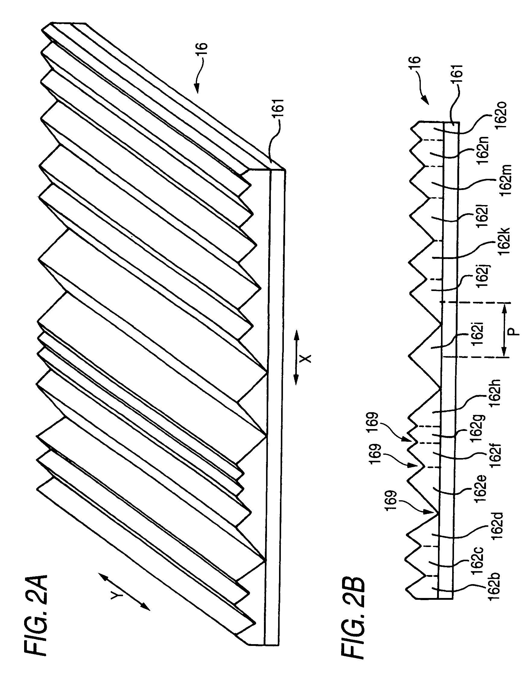
[0040]FIGS. 2A and 2B are diagrams showing the construction of the light condensing filter to describe the first embodiment of the present invention, wherein FIG. 2A is a perspective view, and FIG. 2B is a view taken from in a Y-direction.

[0041]In the light condensing filter 16 of 2B, plural prisms 162b to 162o are continuously formed in the X-direction on one face of the surface of a transparent flat substrate 161 such as a film, a sheet or the like. The transparent flat substrate 161 is formed by using raw material such as glass, plastic or the like. The transparent flat substrate 161 and the plural prisms 162b to 162o may be formed integrally with each other. In this embodiment, the boundary lines of the respective prisms 162b to 162o are represented by vertical lines (in FIG. 2B, represented by broken lines) extending from the respective valley portions 169 (only some of them are represented by reference numeral) of the prisms 162b to 162o to the surface of the...

second embodiment

(Second Embodiment)

[0063]In a light condensing filter of a second embodiment of the present invention, the light condensing filter 16 of the first embodiment becomes the following light condensing filter 16b.

[0064]FIG. 4 is a perspective view showing the construction of a light condensing filter of the second embodiment of the present invention.

[0065]The light condensing filter 16b of FIG. 4 is achieved by forming the prisms 162b to 162o having the same construction as the first embodiment on the opposite surface to the surface of the transparent flat substrate 161. However, the arrangement direction of the prisms 162b to 162o formed on the opposite surface of the transparent flat substrate 161 is perpendicular to the arrangement direction (X-direction) of the prisms 162b to 162o formed on the surface of the transparent flat substrate 161.

[0066]With this construction, the light incident to the light condensing filter 16b can be efficiently condensed, and thus the brightness of the ...


PUM

PropertyMeasurementUnit
top angleaaaaaaaaaa
top angleaaaaaaaaaa
anglesaaaaaaaaaa

Abstract

A light condensing filter has plural prisms formed on a surface of a flat substrate and on the opposite surface to the surface, and light from a light source is condensed by the plural prisms, wherein the plural prisms formed on the surface are designed in a linear shape extending in a specific direction on the surface and arranged in a direction perpendicular to the specific direction, the plural prisms formed on the opposite surface are designed in a linear shape extending in the direction perpendicular to the specific direction on the opposite surface and arranged in the specific direction, and the plural prisms formed on the surface and the plural prisms formed on the opposite surface are irregularly arranged.

Description

[0001]This application is based on Japanese Patent application JP 2004-073969, filed Mar. 16, 2004, the entire content of which is hereby incorporated by reference. This claim for priority benefit is being filed concurrently with the filing of this application.BACKGROUND OF THE INVENTION[0002]1. Technical Field of the Invention[0003]The present invention relates to a light condensing filter in which plural prisms are formed on a substrate and light from a light source is condensed by the plural prisms.[0004]2. Description of the Related Art[0005]A liquid crystal display device varies transmissivity or reflectivity to light by using electro-optical effects such as optical anisotropy, orientation, fluidity and dielectric anisotropy of liquid crystal molecules to thereby display images. This liquid crystal display device is designed to be thin and light and also it has low power consumption, so that it has been broadly used for personal computers, television sets, portable terminals, e...

Claims


Application Information

Patent Timeline
Patent Type & Authority Patents(United States)
IPC IPC(8): G02B5/04G02B27/10F21V8/00G02B1/04G02B5/02G02B6/00G02F1/1335
CPCG02B6/0053G02B6/0061
Inventor NAGAO, KIMITOSHI
Owner FUJIFILM HLDG CORP
Why Eureka
Try Eureka