Door lock transmission mechanism

a transmission mechanism and door lock technology, applied in the direction of keyhole guards, mechanical control devices, instruments, etc., can solve the problems of easy damage to door lock transmission mechanisms and assembly structures thereof, and easy damage to handle bars or push plates. , the effect of reducing maintenance time and maintenance costs

Active Publication Date: 2007-02-27
THASE ENTERPRISE CO LTD
View PDF12 Cites 30 Cited by
  • Summary
  • Abstract
  • Description
  • Claims
  • Application Information

AI Technical Summary

Benefits of technology

[0008]In view of the drawbacks of said prior techniques, an objective of the present invention is to provide a door lock transmission mechanism by which a locking state can be kept, in which a handle bar or a push plate can be forcibly pressed while the door lock is locked, so that the parts of the door lock transmission mechanism can be protected from damage.
[0009]Another objective of the present invention is to provide a door lock transmission mechanism which can actuate a fire-blocking door lock effectively and keep the door lock in a locked state securely.
[0010]Another objective of the present invention is to provide a door lock transmission mechanism, wherein the maintenance time for the door lock can be shortened and the maintenance cost of the door lock can also be reduced by adopting this door lock transmission mechanism.

Problems solved by technology

However, when the fire-blocking door lock according to such patents is locked, an actuating member, such as the handle bar or the push plate, is caught and fixed with inner parts of the door lock transmission mechanism. in other words, when the fire-blocking door lock is locked by a key, the handle bar or the push plate can not be pressed down by users.
Therefore, if the handle bar or the push plate is malevolently struck, the inner parts of the door lock transmission mechanism and the assembly structure thereof may be damaged.
Accordingly, while such conventional door lock transmission mechanism is locked, the parts of the door lock transmission mechanism and the assembly structure thereof may easily fail to function due to the aforementioned vulnerability.
Meanwhile, because the parts of the conventional door lock transmission mechanism and the assembly structure thereof may be easily damaged, higher maintenance costs and more maintenance time result.
Moreover, because of the high failure rate of such door lock transmission mechanism, the operational efficiency of the door lock may be reduced, thereby adversely affecting operation.
Therefore, said conventional door lock transmission mechanism is not only disadvantageous in terms of maintenance and operation, but also inclined to influence the normal safety function of the fire-blocking door lock due to the operational problems.
Furthermore, due to the lack of flexibility of the structural design of the foregoing conventional door lock transmission mechanism, said door lock transmission mechanism can only be applied to specific fire-blocking door locks compatible with its design principles.
Therefore, the application of the conventional door lock transmission mechanism is restricted to only a few types of fire-blocking door locks, lacking applicability to many types of fire-blocking door locks.
From the foregoing description, because the handle bar or the push plate of said conventional door lock transmission mechanism is easily damaged by excess external force, not only the problems of maintenance, cost, and operation may be induced, but also the effective actuation of the fire-blocking door lock may be obstructed by vulnerable parts of the door lock transmission mechanism, so that users may be endangered.

Method used


Image

  • Door lock transmission mechanism
  • Door lock transmission mechanism
  • Door lock transmission mechanism

Examples


first embodiment

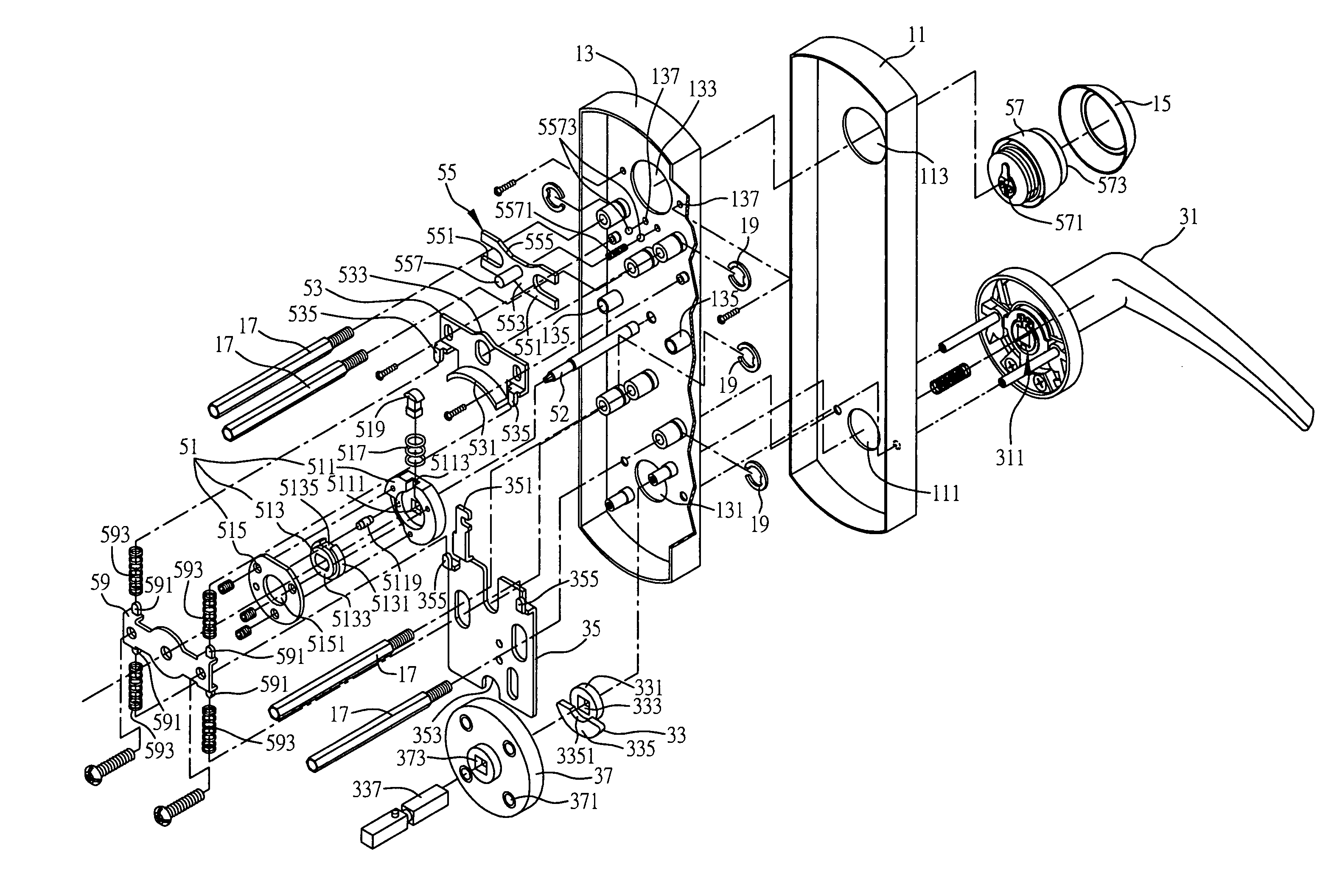
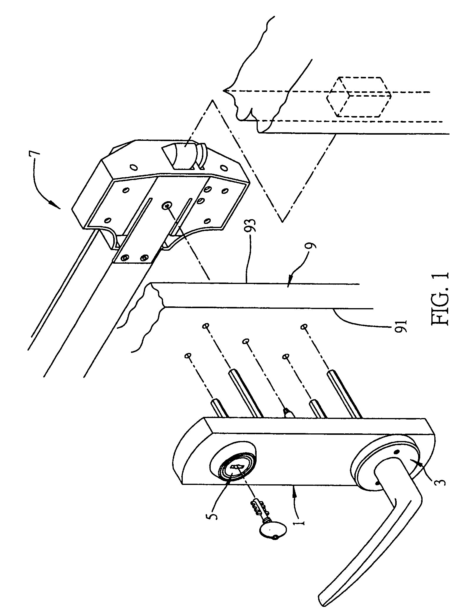
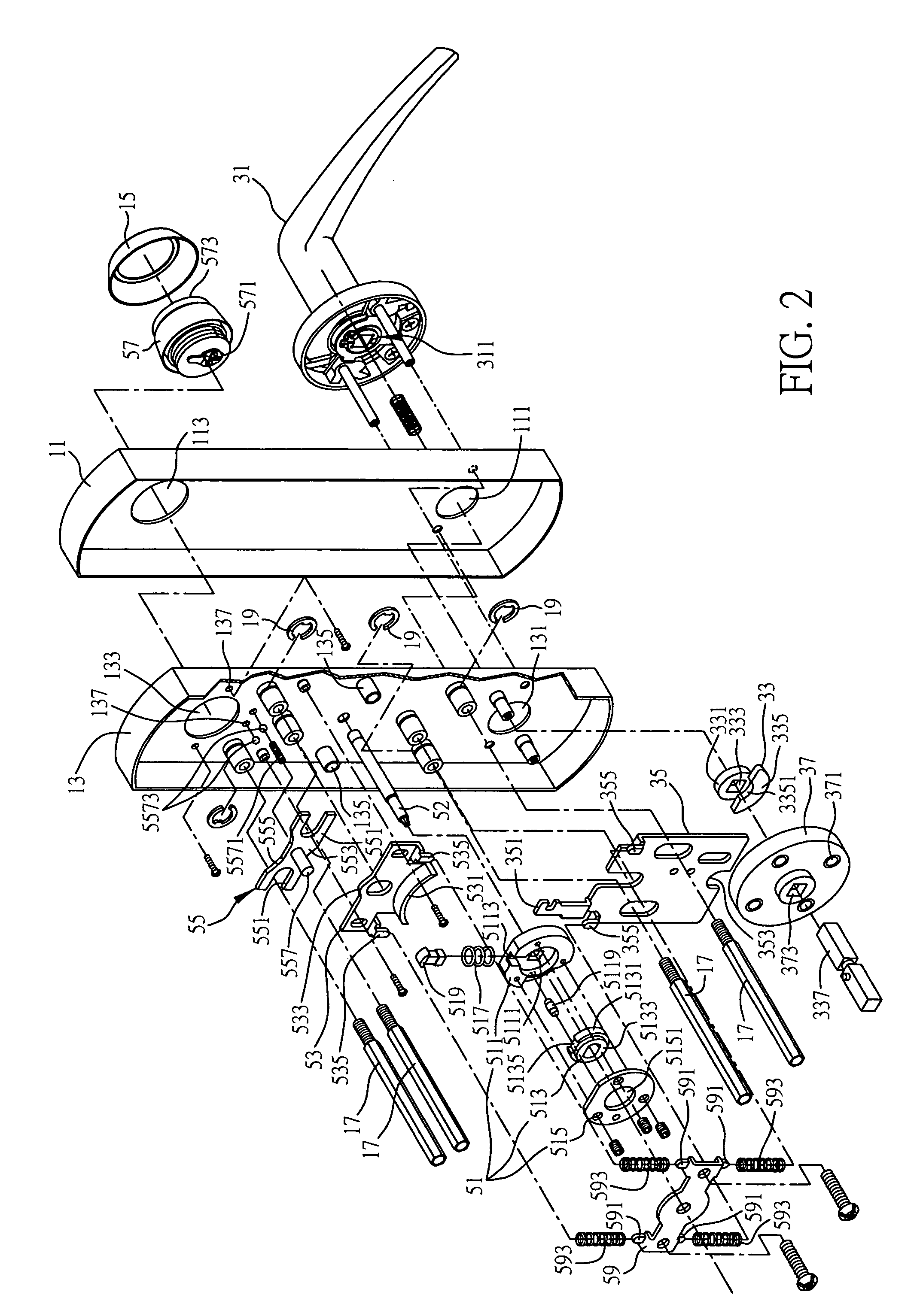
[0034]FIG. 1 to FIG. 6 shows the first embodiment of the door lock transmission mechanism according to the present invention. Referring to FIG. 1, the door lock transmission mechanism according to the present invention mainly comprises a door lock casing unit 1, an actuation mechanism 3, and a locking mechanism 5. It should be noted that this embodiment of the door lock transmission mechanism of the present invention is described with an example in which the door lock transmission mechanism is assembled to a door 9 with a fire-blocking door lock 7. As shown in the drawing, the door lock transmission mechanism according to the present invention is installed on the first surface 91 of the door 9, for transmitting movement to the door lock 7 mounted on the second surface 93 of the door 9 opposite to the first surface 91.

[0035]The present invention can be applied to both the conventional fire-blocking door lock and door without changing the structure thereof. Therefore, for simplifying ...

second embodiment

[0056]FIG. 7 to FIG. 10 illustrate the second embodiment of the door lock transmission mechanism of the present invention. The function of the door lock transmission mechanism according to this embodiment is similar to that according to the pervious embodiment, and hence only the differing structure and function are described, omitting the description of alike features, in order to make the features and advantages of the present invention more apparent. Similar or same components are denoted with similar or same reference numerals.

[0057]As shown in FIG. 7, the key differences between this embodiment and the foregoing first embodiment is that the actuation mechanism 3 comprises an actuation member 31′ such as a push plate, a pair of fixing pieces 33′, and a traction member 35′. As shown in FIG. 8, the two sides of the actuation portion 311′ of the actuation member 31′ are connected to a pair of pivot pins 313′. Each of the pivot pins 313′ has a ring groove 3131′ by which the actuatio...


PUM


Abstract

A door lock transmission mechanism is provided on the first surface of a door for transmitting movement to a door lock provided on the second surface of the door opposite to the first surface. The door lock transmission mechanism includes a lock casing unit, an actuation mechanism, and a locking mechanism. The actuation mechanism includes a traction member having a traction portion for driving a locking seat of a core unit of the locking mechanism, wherein the locking seat can rotate freely when the locking mechanism is locked, such that an actuation member of the actuation mechanism can be pressed down by force and keeps the locking state of the door lock, and thus the parts of the door lock transmission mechanism can be protected from being damaged.

Description

FIELD OF THE INVENTION[0001]The present invention relates to a door lock transmission mechanism, and more particularly, to a door lock transmission mechanism provided on one side of a door for transmitting movement to a door lock provided on the other side of the door to open the door.BACKGROUND OF THE INVENTION[0002]A general fire-blocking door lock structure is installed on one side of a fire-blocking door, with a frame member horizontally mounted on the center of the fire-blocking door. By pushing a push plate contained within the frame member, a mechanism inside a door lock casing unit is driven to move downwardly, causing a latch to be drawn back to release the locking state of the door lock, thereby opening the door.[0003]Moreover, a door lock transmission mechanism which comprises a handle bar (or a push plate) and / or a lock barrel is installed on the other side of the door. Users can unlatch the fire-blocking door lock to open the door from the other side of the door by push...

Claims


Application Information

Patent Timeline
Patent Type & Authority Patents(United States)
IPC IPC(8): E05B55/04E05B65/10E05B13/00
CPCE05B65/1046E05B13/005Y10T70/5159Y10T70/5416Y10T70/5805
Inventor LIN, CHING-TIEN
Owner THASE ENTERPRISE CO LTD
Why Eureka
Try Eureka