Eureka AIR delivers breakthrough ideas for toughest innovation challenges, trusted by R&D personnel around the world.

Personal flight vehicle and system

a flight vehicle and personal technology, applied in the field of flight systems, can solve the problems of inability to sustain safely or for any functional duration, require a tremendous amount of fuel, and die in failure, and achieve the effect of improving air quality

Inactive Publication Date: 2007-02-27
REDMOND SCOTT D
View PDF54 Cites 21 Cited by
  • Summary
  • Abstract
  • Description
  • Claims
  • Application Information

AI Technical Summary

Benefits of technology

"The patent describes a device that uses electricity to lift a person up. It uses two capacitive plates that generate a force in a specific direction. An ion conditioner is used to improve the air around the plates. The technical effect is a more efficient and safe way to lift people using electricity."

Problems solved by technology

Some current solutions rely on traditional rocket based thrust which cannot be sustained safely or for any functional duration and propellers which are unsafe and require a tremendous amount of fuel to achieve and maintain lift capability and maneuverability.
These rocket based flight systems can cause dismemberment and death upon failure and throw metal violently upon mishap.
The fluid and electromechanics to operate them may be fragile and difficult to maintain.
Typically, the systems to operate these rocket based flight systems are so complex and the forces involved so great that only specialized, heavily trained personnel can operate them.
Some propellers based flight systems may cause dismemberment and death upon contact and throw blades violently upon mishap.
Usually propellers require tremendous mechanical effort to turn on and maintain velocity.
Propellers require heavy engines to power them.
Propellers may require a tremendous amount of fuel to achieve and maintain lift capability and maneuverability.
Both of the above systems can require runways, a great amount of space, and be uncomfortably noisy to a human user.
Another shortcoming of a high voltage Ion-Wind based propulsion system is unshielded systems during operation produce a significant amount of X-Radiation.
While exposure of this sort can be shielded with advanced materials and by engineering the passenger compartment to be distanced from the source of X-Ray emissions, any ion-wind technology utilizing high-levels of both voltage and current will rapidly produce unreasonably high amounts of X-radiation.
Ion-wind is seldom as clean as it looks, in that quite often static electricity builds up on nearby surfaces, causing damage to instrumentation and in some cases even a dangerous shock potential.

Method used


Image

  • Personal flight vehicle and system
  • Personal flight vehicle and system
  • Personal flight vehicle and system

Examples


Embodiment Construction

[0039]In the following description, numerous specific details are set forth, such as examples of specific data signals, named components, connections, number of memory columns in a group of memory columns, etc., in order to provide a thorough understanding of the present invention. It will be apparent, however, to one of ordinary skill in the art that the present invention may be practiced without these specific details. In other instances, well known components or methods have not been described in detail but rather in a block diagram in order to avoid unnecessarily obscuring the present invention. Thus, the specific details set forth are merely exemplary. The specific details may be varied from and still be contemplated to be within the spirit and scope of the present invention. The term coupled is defined as meaning connected either directly to a component or indirectly through another component.

[0040]In general, various methods, apparatuses, and systems are described in which an...


PUM


Abstract

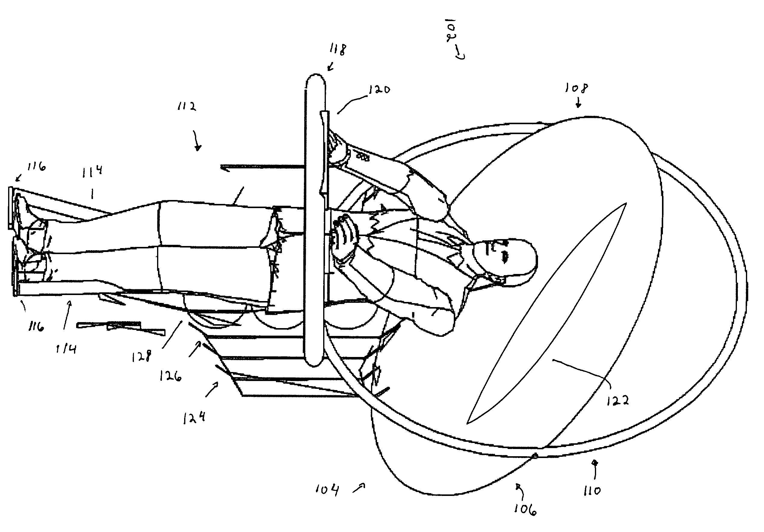
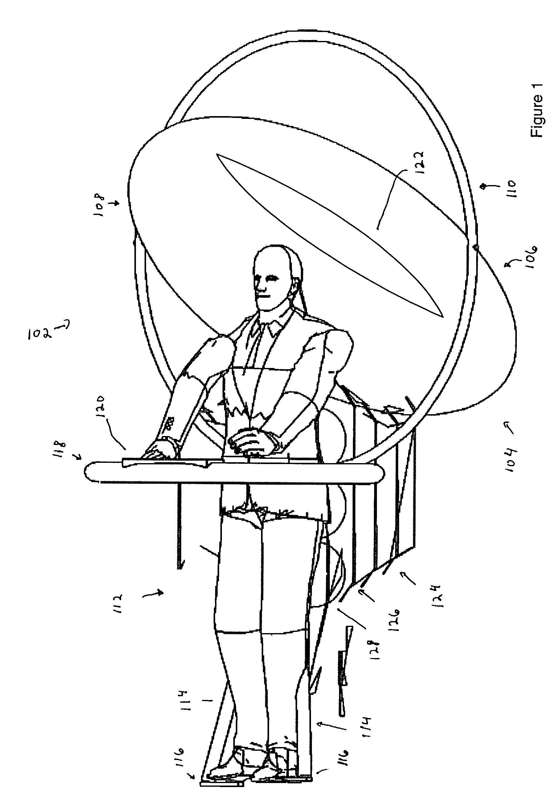
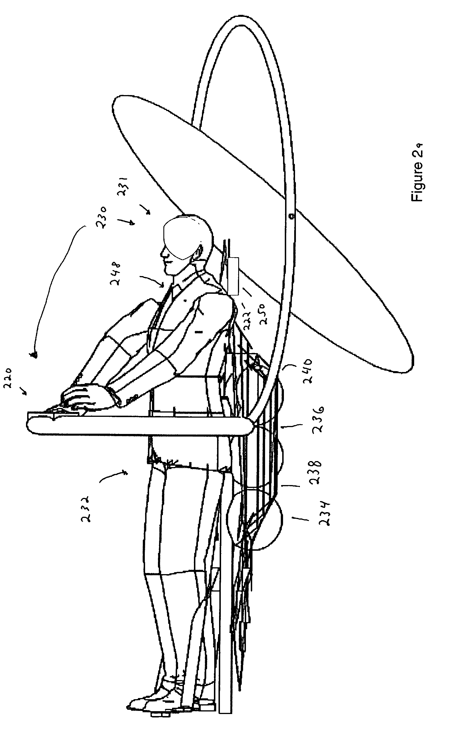
Various methods, apparatuses, and systems in which an electric-energy lifting panel levitates a user secured to the electric-energy lifting panel. The electric-energy lifting panel includes a first capacitive plate and a second capacitive plate having different geometric dimensions to generate a net-directional force. An ion conditioner ion enhances air around the first capacitive plate and the second capacitive plate.

Description

FIELD OF THE INVENTION[0001]Embodiments of the invention generally relate to flight systems. More particularly an aspect of this invention relates to a flight vehicle levitating a user via electric energy.BACKGROUND OF THE INVENTION[0002]Systems which allow a user to fly above the earth or in space exist today. Some current solutions rely on traditional rocket based thrust which cannot be sustained safely or for any functional duration and propellers which are unsafe and require a tremendous amount of fuel to achieve and maintain lift capability and maneuverability.[0003]These rocket based flight systems can cause dismemberment and death upon failure and throw metal violently upon mishap. The fluid and electromechanics to operate them may be fragile and difficult to maintain. Typically, the systems to operate these rocket based flight systems are so complex and the forces involved so great that only specialized, heavily trained personnel can operate them.[0004]Some propellers based ...

Claims


Application Information

Patent Timeline
Patent Type & Authority Patents(United States)
IPC IPC(8): B64G1/00B64C39/00B64C39/02B64D27/24
CPCB64C39/00B64C39/001B64D27/24B64C39/026Y02T50/62Y02T50/44Y02T50/40Y02T50/60B64C29/04
Inventor REDMOND, SCOTT D.
Owner REDMOND SCOTT D
Why Eureka
Eureka Blog
Learn More