
Nanoliter osmometer and method of operation

a technology of osmometer and nanoliter, applied in the field of nanoliter osmometer and method of operation, can solve the problem of complicated handling of nanoliter samples, and achieve the effect of enhancing the measurement of temperatur

Inactive Publication Date: 2007-02-27
ADVANCED INSTR LLC
View PDF21 Cites 5 Cited by
  • Summary
  • Abstract
  • Description
  • Claims
  • Application Information

AI Technical Summary

Benefits of technology

"The present invention provides an apparatus for measuring the temperature at which a phase change occurs in a sample. The apparatus includes a sample cell for direct collection of the sample, a heating and cooling assembly, and an illumination system. The sample cell has a longitudinal passage through which light is transmitted to provide an image of the sample. The apparatus can be used to measure the osmolality of human body fluids such as tears. The sample cell is designed to collect and retain the sample at the collecting end by capillary attraction, and the cross-sectional area of the passage is greater at the collecting end to improve the consistency of the temperature measurement. The method involves positioning the sample cell in contact with the sample source to collect the sample by capillary attraction, and cooling the sample within the cell to cause a first phase change. The apparatus and method provide a more accurate and repeatable way to measure the temperature at which a phase change occurs in a sample."

Problems solved by technology

Handling of nanoliter samples is complicated by the physical size of the sample.

Method used


Image

  • Nanoliter osmometer and method of operation
  • Nanoliter osmometer and method of operation
  • Nanoliter osmometer and method of operation

Examples


Embodiment Construction

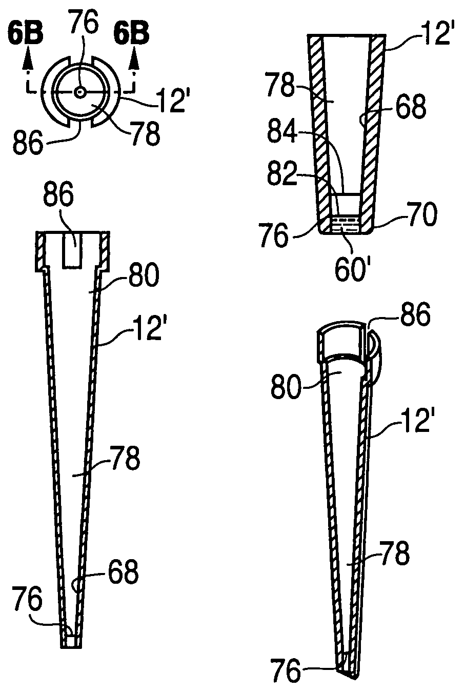
[0025]The present invention provides an improved osmometer, method of operation and sample cell which may be practiced using Assignee's prior osmometer as described in FIGS. 1–4, but is not limited thereto. The sample cell, as illustrated in FIGS. 6A–6E, may be utilized in a modified version of the prior art of FIGS. 1–4 to achieve the benefits of the invention.

[0026]FIGS. 6A–6E illustrate the views of the sample cells 12′ in accordance with the present invention. The sample cell 12′ is constructed from a plastic material, such as polypropylene, having molecular and surface characteristics which promote the direct collection of samples at the tip of the sample cell as the result of capillary attraction or other attraction phenomenon between the sample 60′, and the walls 68 of the tip of the sample cell at the collecting end 70 thereof. The collecting end 70 is inserted directly into contact with the sample to be collected, such as at the corner of the human eye 74. The tip 70 prefer...


PUM

PropertyMeasurementUnit
thicknessaaaaaaaaaa
thicknessaaaaaaaaaa
volumeaaaaaaaaaa

Abstract

The invention is an apparatus for determining a temperature at which a phase change occurs in a fluid sample, a method for measuring a temperature at which a phase change occurs in a sample and a sample cell. An apparatus for determining a temperature at which a phase change occurs in a fluid sample 60′ in accordance with the invention includes a sample cell (12′)for providing direct collection of the sample from a sample source (74) which is collected and retained at a collecting end thereof by capillary attraction between the collecting end and the sample, the sample cell including a longitudinal passage (78) extending from the collecting end to a far end through which light is transmitted to provide an image of the sample as retained at the collecting end of the passage and with a cross sectional area of the passage being greater at the far end than at the collecting end; a heating and cooling assembly (14), including a temperature sensing device (44), the heating and cooling assembly holding and thermally contacting the sample cell during the determining of the temperature by the temperature measuring device at which the phase change occurs while the sample is positioned in the collecting end; and an illumination system (16) for directing a light beam to the collecting end, through the sample, through the longitudinal passage and out of the far end to permit viewing of the sample from the far end to determine the temperature at which the phase change occurs.

Description

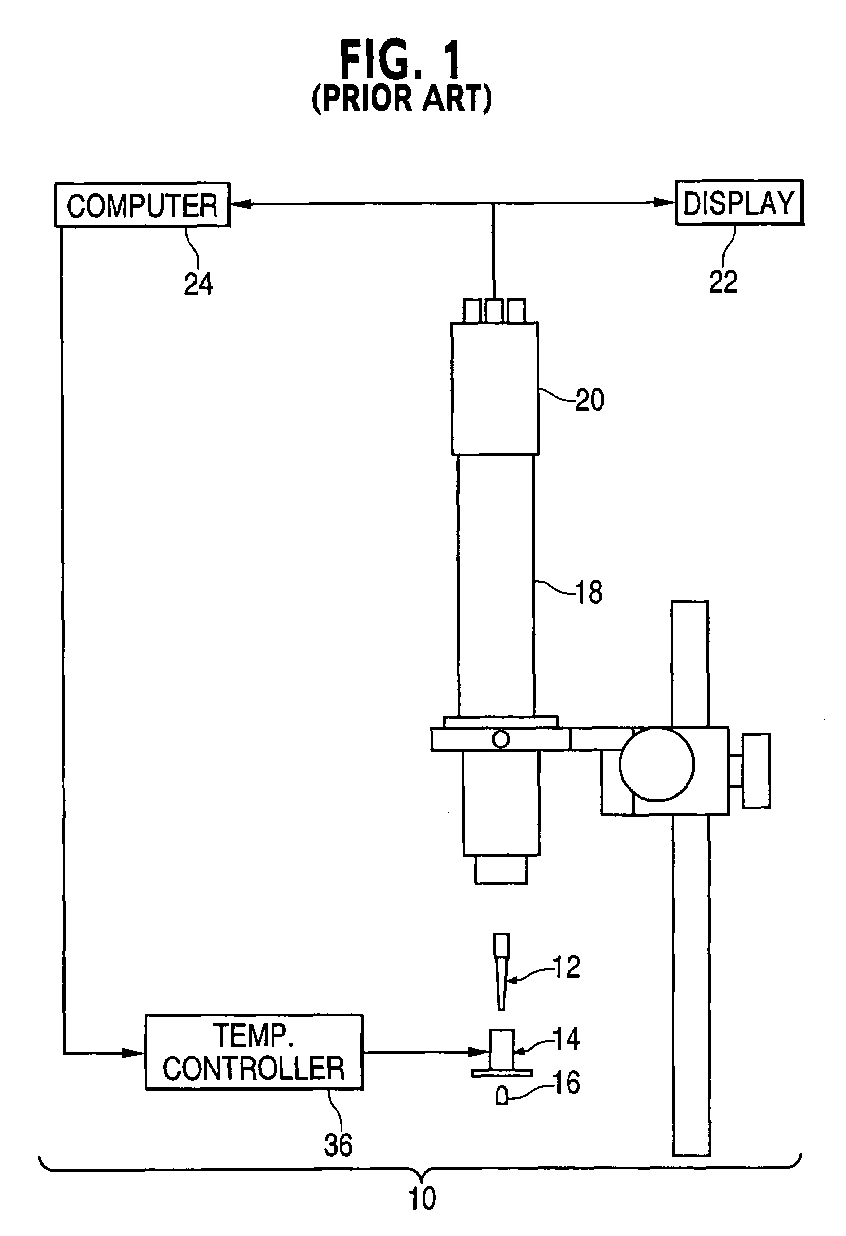
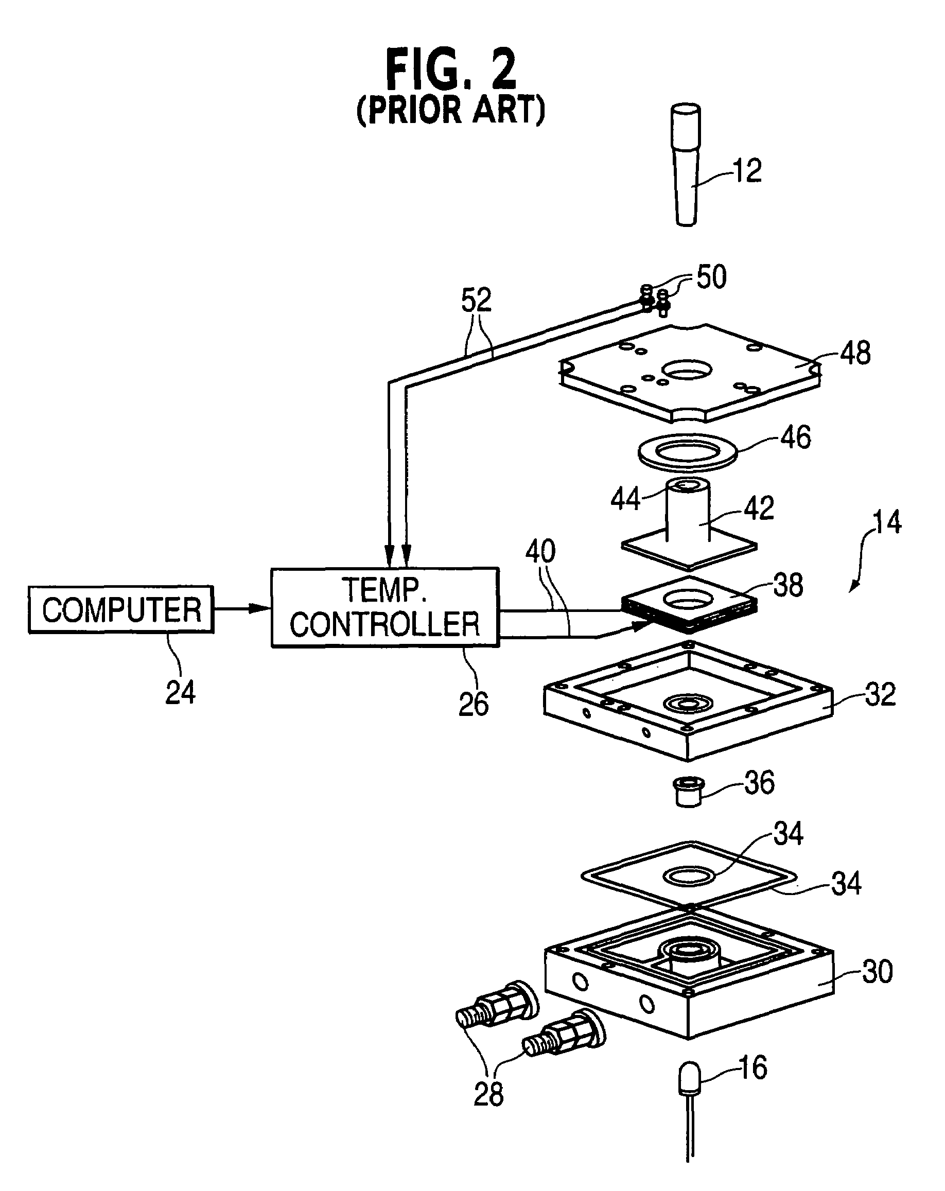
BACKGROUND OF THE INVENTION[0001]The present invention relates to the determination of the temperature at which a phase change occurs in a fluid sample such as, but not limited to, osmometers and the method of use thereof.DESCRIPTION OF THE PRIOR ART[0002]Recently, interest has developed in using osmometry on extremely small samples of fluid, such as, a sample of a human eye tear. Handling of nanoliter samples is complicated by the physical size of the sample. One prior art technique utilizes a plate containing depressions which hold portions of the sample. This technique recognizes the last portion of the sample to melt with reflective light technology.[0003]The Assignee has developed an osmometer as described below with respect to FIGS. 1–5A–5C. The osmometer described below of the Assignee, while functioning to determine the point of phase change from a frozen tear sample to liquid did, not have the desired ease of use.[0004]FIG. 1 illustrates a system diagram of the prior art na...

Claims


Application Information

Patent Timeline
Patent Type & Authority Patents(United States)
IPC IPC(8): A61B5/01G01N13/04G01N25/04G01N33/48
CPCG01N25/06G01N13/04
Inventor CORBETT, CHRISTOPHER J.
Owner ADVANCED INSTR LLC
Learn More