Additive dispersing filter and method of making

a technology of additive dispersing filter and additive dispersing filter, which is applied in the direction of lubricant mounting/connection, separation process, packaging goods, etc., can solve the problems of increased engine wear, depletion, and contamination formation, and achieve the effect of prolonging the useful life of engine oil and prolonging the time interval

Inactive Publication Date: 2007-02-27
BMO HARRIS BANK N A AS SUCCESSOR COLLATERAL AGENT +1
View PDF86 Cites 71 Cited by
  • Summary
  • Abstract
  • Description
  • Claims
  • Application Information

AI Technical Summary

Benefits of technology

[0017]The apparatus according to the invention may also include a baffle for directing oil flow, and the additive cartridge may be attached to the baffle. Where the baffle is used, a dividing wall may be provided between the baffle and the additive chamber.
[0018]The additive cartridge has at least one opening, and may have a limited number of openings therein to control the rate of diffusion therefrom.
[0019]Accordingly, exemplary embodiments of the present invention provide an oil filter including one or more beneficial oil additives that are released slowly over the life of the filter.

Problems solved by technology

In the oil filtration art, it is well known that normal operation of an internal combustion engine, particularly a diesel engine, results in the formation of contaminants.
These contaminants are typically introduced into the lubricating oil during engine operation, and tend to increase oil viscosity and generate unwanted engine deposits, leading to increased engine wear.
These work well for a short period, but may become depleted.
Additionally, due to the solubility and chemical stability limits of these dispersants in the oil, the service lives of the lubricating oil and the oil filter are less than optimal.
The depletion of the TBN is an important limiting factor for many internal combustion engines, and in particular for heavy-duty applications with diesel engines.
The inclusion of these further additives may be beneficial; however, with conventional methods, the amount and concentration of these additives are limited by the ability of lubricating oils to suspend these additives, as well as by the chemical stability of these additives in the oil.
Another problem with many of the known filter designs is that beneficial additives are added to the oil before the oil is mechanically filtered through a filter element.

Method used


Image

  • Additive dispersing filter and method of making
  • Additive dispersing filter and method of making
  • Additive dispersing filter and method of making

Examples


second embodiment

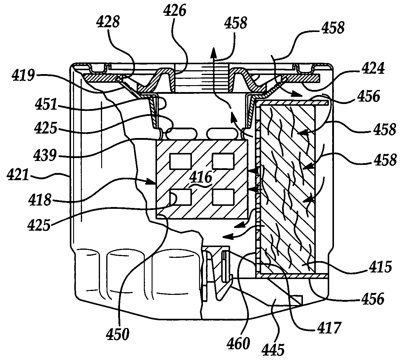
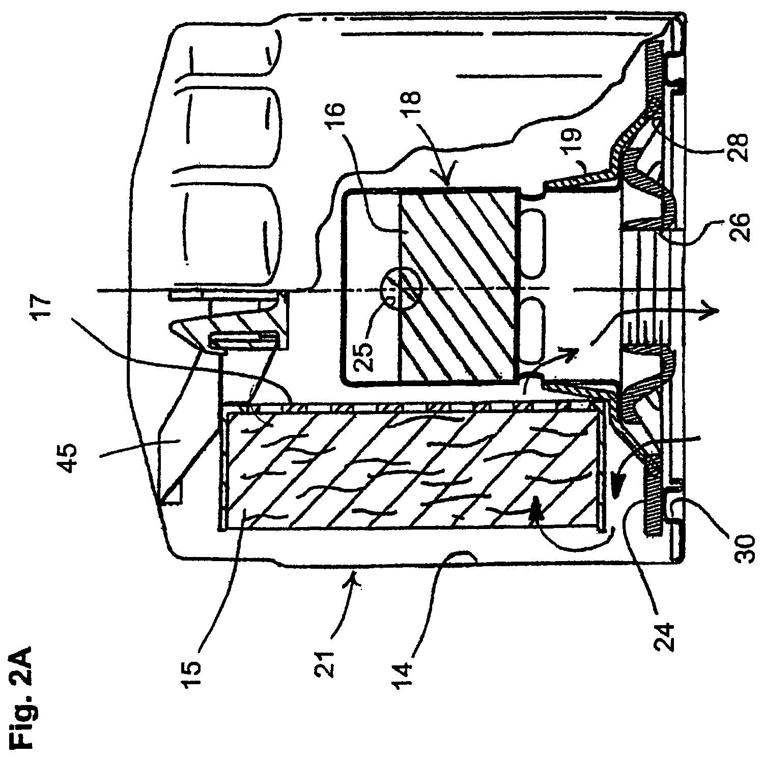
[0065]Referring now to FIG. 6, an additive cartridge 218 in accordance with the invention is shown. Unless specified or depicted as being different herein, the additive cartridge 218 is substantially similar to the additive cartridge 18 as previously described. Those in the art will understand that the additive cartridge 218 of FIG. 6 may be substituted into the oil filter 20 of FIG. 2A instead of the additive cartridge 18 thereof, located above the center tube as indicated by FIG. 6.

first embodiment

[0066]The cartridge 218 in this embodiment includes a hollow cartridge shell 235 in the form of a basket. The shell 235 is either supported by or otherwise attached to the center tube 217. While the center tube 217 is shown in simplified form in the drawings, it will be understood that it is a porous member. The shell 235 may include a top flange 219 for connecting to the center tube. The shell 235 has a recessed space formed in the top thereof for supportively receiving a retainer spring 245. The shell 235 also has one or more openings 225 formed therein to allow fluid communication with between the interior thereof and the space surrounding the shell. A solid additive concentrate 216 is provided inside of the shell 235, in a manner similar to that described above for the The additive may be in one piece or may be pelletized.

third embodiment

[0067]Referring now to FIG. 8, an additive cartridge 318 in accordance with the invention is shown. Unless specified or depicted as being different herein, the additive cartridge 318 is substantially similar to the additive cartridge 18 as previously described. Those in the art will understand that the additive cartridge 318 of FIG. 8 may be substituted into the oil filter 20 of FIG. 2A instead of the additive cartridge 18 and center tube 17 thereof.

[0068]The cartridge 318 in this embodiment is a modified center tube. In the embodiment of FIGS. 6–7, the cartridge 318 includes a hollow cylindrical shell 335 with a solid additive 316 contained therein. The shell 235 also has one or more openings 325 formed therein to allow fluid communication with between the interior thereof and the space surrounding the shell. A solid additive concentrate 316 is provided inside of the shell 235, in a manner similar to that described above for the first embodiment. The additive may be in one piece or...


PUM

PropertyMeasurementUnit
pressureaaaaaaaaaa
areaaaaaaaaaaa
diameteraaaaaaaaaa

Abstract

An oil-conditioning filter, for use with an internal combustion engine, includes a filter element and an additive cartridge, for gradually dispensing an oil additive over time. The additive cartridge has a beneficial oil-conditioning agent contained therein. Placement of the cartridge allows for fluid filtration through the filter element before fluid communication with the additive of the additive cartridge. An additive dispersing member is also described.

Description

CROSS REFERENCE TO RELATED APPLICATIONS[0001]The present application is a continuation-in-part of application Ser. No. 10 / 352,344, filed Jan. 27, 2003, now U.S. Pat. No. 7,018,351 which is a continuation in part of Ser. No. 09 / 867,973, filed May 30, 2001, which is a continuation in part of Ser. No. 09 / 566,034 filed May 8, 2000, now abandoned the contents of each of the aforementioned applications are incorporated herein by reference thereto.TECHNICAL FIELD[0002]The present invention relates to a filter for a fluid and a method for making the same.BACKGROUND[0003]Many different types of fluid filters are known. Most such filters use a mechanical or ‘screening’ type of filtration, with a porous filter element disposed therein. The oil is repeatedly cycled through the filter element to remove impurities.[0004]In the oil filtration art, it is well known that normal operation of an internal combustion engine, particularly a diesel engine, results in the formation of contaminants. These c...

Claims


Application Information

Patent Timeline
Patent Type & Authority Patents(United States)
IPC IPC(8): B65B1/04B01D27/02B01D27/10B01D37/02C10M175/00
CPCB01D27/00B01D27/02B01D27/103B01D37/025C10M175/00C10M175/0091B01D27/106Y10S210/17F01M9/02F01M11/03F01M2001/1014B01D37/02B01D39/00
Inventor EILERS, DEREKBILSKI, GERARD W.AUXTER, DANIEL J.ZULAUF, GARY B.LYNCH, MICHAEL S.TREIER, PHILIP
Owner BMO HARRIS BANK N A AS SUCCESSOR COLLATERAL AGENT
Why Eureka
Try Eureka