Compact antenna with directed radiation pattern

a radiation pattern and antenna technology, applied in the field of communication, can solve the problems of almost entirely inductive coupling between the reader antenna and the tag antenna, and the pc card rfid reader

Active Publication Date: 2007-02-27
WJ COMM
View PDF4 Cites 44 Cited by
  • Summary
  • Abstract
  • Description
  • Claims
  • Application Information

AI Technical Summary

Problems solved by technology

RFID systems operating at the low-frequency ranges are widely used and are inexpensive, but have the fundamental disadvantage that coupling between the reader antenna and the tag antenna is almost entirely inductive.
The making of a PC Card RFID reader, however, presents many challenges, one of them is associated with the design of a suitable antenna.

Method used


Image

  • Compact antenna with directed radiation pattern
  • Compact antenna with directed radiation pattern
  • Compact antenna with directed radiation pattern

Examples


example 1

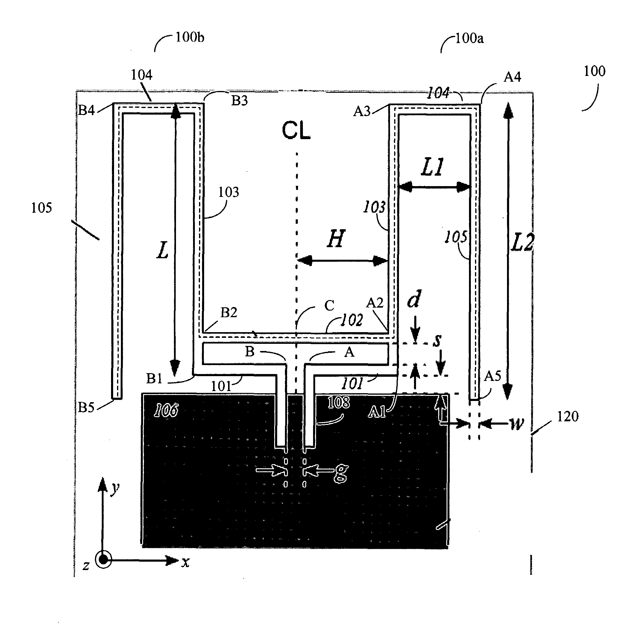
[0070]FIG. 21 illustrates a circuit board layout of antenna 100 according to one embodiment of the present invention. Antenna 100 in FIG. 11 is constructed on a printed circuit board 120 using parameters given in Table 1. These parameters are chosen to provide good matching and radiation in the US industrial, scientific, and medical (ISM) band having a frequency range from 902 MHz to 928 MHz. FIG. 21 also shows an input line 112 for receiving a single-ended radio signal and a conventional wire-wound balun 113 employing a ferrite core and bifilar winding, which is employed to provide a transition between the single-ended input line 112 and antenna 100. Discrete matching components including a capacitor 114 inserted in input line 112, an inductor 115 coupled between input line 112 and ground plane 106, and a capacitor 116 coupled between terminals A and B of conductor lines 100a and 100b of antenna 100 are also provided to compensate for effects caused by imperfection of balun 113.

[00...

example 2

[0079]A test antenna was constructed to examine the effects of the dimensions and placement of a plastic enclosure (‘radome’). The dimensions of this antenna are shown in Table 2. FIG. 28 explains the nomenclature describing the radome configuration.

[0080]

TABLE 2ParameterValueUnitsSubstrateFR4(NA)Substrate thickness710micronsL31mmH11mmL19mmL232mmg3.6mmd2mms3.5mmw1.3mmBottom Cavity0.7mmHeightRadome3(NA)dielectric constant

[0081]The effects of the radome is examined by simulations using a variety of differing radome configurations. The simulation results for different cases of antenna radome configuration are summarized in Table 3.

[0082]

TABLE 3ResonantRe(Zin) atTopBottomTopSideFrequencyResonantCavity HeightThicknessThicknessThickness[MHz]FrequencyCases[mm][mm][mm][mm]Im(Zin = 0 Ω)[Ω]16.61.301.301.309486026.60.650.650.659746736.61.300.650.659616146.60.651.301.309626556.60.650.651.309656662.31.301.301.309435572.30.650.650.65972638No Radome1011 76

[0083]A regression fit to the simulations ...


PUM


Abstract

The present invention includes a balanced compact antenna, conforming to the envelope restrictions appropriate to a PC-card form factor, with maximum radiation intensity along a long axis of the card. The inventive antenna configuration employs an inductive shorting bar to match an “M”-shaped bent dipole antenna to a differential feed. The combination of horizontal cross-members and large vertical downward legs ensures radiation predominantly in a broadside direction while keeping the dimensions of the antenna sufficiently compact to fit within the PC-card envelope.

Description

CROSS REFERENCE TO RELATED APPLICATIONS[0001]The present application claims the benefit of and priority to U.S. Provisional Patent Application Ser. No. 60 / 630,509, filed on Nov. 22, 2004, the entire disclosure of which is incorporated herein by reference.FIELD OF THE INVENTION[0002]The present invention is related to communications using radio frequency signals, and more particularly to an improved compact antenna having a forward-directed radiation pattern.BACKGROUND[0003]Radio Frequency Identification (RFID) technologies are widely used for automatic identification. A basic RFID system includes an RFID tag or transponder carrying identification data and an RFID interrogator or reader that reads and / or writes the identification data. An RFID tag typically includes a microchip for data storage and processing, and a coupling element, such as an antenna, for communication. An RFID reader operates by writing data into the tags or interrogating tags for their data through a radio-freque...

Claims


Application Information

Patent Timeline
Patent Type & Authority Patents(United States)
IPC IPC(8): H01Q9/28
CPCH01Q1/22H01Q9/40H01Q1/2275
Inventor WEIGAND, STEVEN
Owner WJ COMM
Why Eureka
Try Eureka