Glow plug with combustion pressure detecting function

a technology of combustion pressure and glow plug, which is applied in the direction of instruments, lighting and heating apparatus, machines/engines, etc., can solve the problems of dispersing sensitivity of combustion pressure sensors and failing to achieve the proper detecting output, etc., and achieves high reliability, easy handling, and strong sensitivity.

Inactive Publication Date: 2007-03-06
NGK SPARK PLUG CO LTD
View PDF12 Cites 14 Cited by
  • Summary
  • Abstract
  • Description
  • Claims
  • Application Information

AI Technical Summary

Benefits of technology

[0006]In addition, the glow plug having the combustion pressure detecting function may be configured such that the piezoelectric element is arranged between that face of the root-end portion of the housing, which confronts the leading-end side, and that face on the center pole on the leading-end side, which confronts the root-end side. On the contrary to the glow plug having the combustion pressure detecting function of JP-A-2002-327919, the glow plug having the combustion pressure detecting function of that type increases the preload to be applied to the piezoelectric element, in case it is mounted in the internal combustion engine, so that the sensitivity of the combustion pressure sensor rises.
[0061]In the glow plug having the combustion pressure detecting function of the invention, the ring-shaped sealing member is arranged on the leading-end side of the first piezoelectric element and the second piezoelectric element, as viewed in the axial direction, and the space, as located closer to the sides of the first piezoelectric element and the second piezoelectric element than the sealing member, between the outer side face of the center pole and the inner side face of the housing, is made gastight with respect to the space on the leading-end side of the sealing member. Even if the combustion gas invades from the leading-end side into the space between the center pole and the inner side face of the housing, the gas does not reach the portions of the first piezoelectric element and the second piezoelectric element. As a result, the first piezoelectric element and the second piezoelectric element do not receive the stress from the pressure of the combustion gas so that their outputs are not influenced. As a result, the glow plug having the combustion pressure detecting function of the invention can provide a proper combustion pressure detection output.

Problems solved by technology

As a result, the sensitivity of the combustion pressure sensor may disperse to fail to achieve the proper detecting output.

Method used


Image

  • Glow plug with combustion pressure detecting function
  • Glow plug with combustion pressure detecting function
  • Glow plug with combustion pressure detecting function

Examples


embodiment 1

[Embodiment 1]

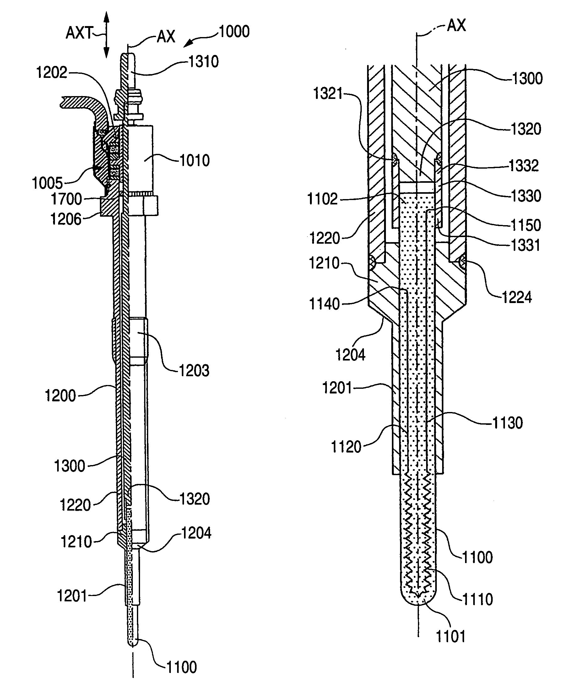
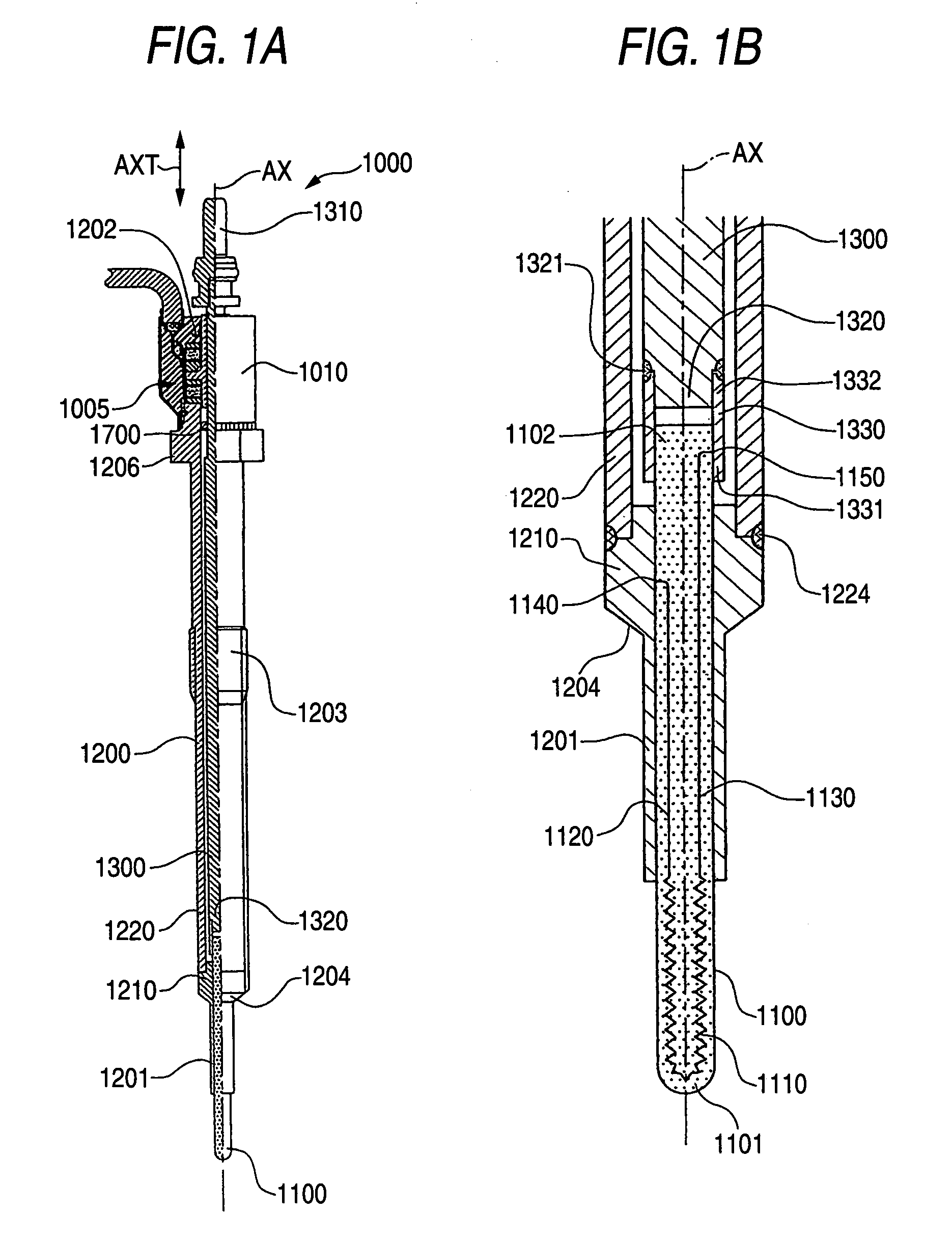
[0143]First of all, a first embodiment of the invention is described with reference to FIGS. A glow plug 1000 is one capable of heating a heater member 1100 for aiding, when energized, in the start of an internal combustion engine, and having a combustion pressure sensor 1005 configured to detect the change in the combustion pressure of the internal combustion engine. This glow plug 1000 is equipped, as shown in FIG. 1A, with: a cylindrical housing 1200 extending in a direction AXT (as will be simply called the “axial direction”) along an axial line AX; a conductive center pole 1300 held in the housing 1200; and the heater member 1100 arranged on the axially leading-end side (as located on the lower side and will be simply called the “leading-end side”) of the center pole 1300.

[0144]As shown in FIG. 1B, this heater member 1100 is formed to have a substantially semispherical shape at a heater leading-end portion 1101 and to have a rod shape made of ceramics of silicon n...

modification 1

(Modification 1)

[0249]Next, a first modification of Embodiment 1 is described with reference to FIG. 16. The foregoing Embodiment 1 has used the heater member 1100 having the heater heating portion 1110 made of a non-metallic heating element, i.e., the so-called ceramic heater. On the contrary, a glow plug 5000 of Modification 1 is different in that it uses a sheath member 5100 having a heater member 5101 made of a metallic heating element. Therefore, the description is made only on the different portions, but the description on similar portions is omitted.

[0250]FIG. 16 is an enlarged section of a leading-end portion of the glow plug 5000. This glow plug 5000 is equipped with a cylindrical housing 5200 extending in the axial direction; a center pole 5300 held in the housing 5200; and the sheath member 5100 holding the coil-shaped heater member 5101 therein and having its leading end (or the lower end in FIG. 16) closed in a substantially semispherical shape.

[0251]The heater member 5...

modification 2

(Modification 2)

[0257]A second modification of Embodiment 1 is described with reference to FIG. 17. In the foregoing Embodiment 1, the combustion pressure sensor 1005 has used the ring-shaped first and second piezoelectric elements 1400 and 1500, which are polarized in the polarizing direction PLT parallel to the axial direction AXT along the axis AX.

[0258]On the other hand, a glow plug 2000 of Modification 2 is substantially similar except that its combustion pressure sensor 2005 uses first and second piezoelectric elements 2400 and 2500, which are polarized in a radial direction perpendicular to the axis AX. Therefore, the description is made only on the different portions, but the description on similar portions is omitted.

[0259]FIG. 17 is an explanatory view for explaining the actions of the combustion pressure sensor 2005 of the glow plug 2000 while simplifying the longitudinal section of the combustion pressure sensor 2005 partially.

[0260]In this combustion pressure sensor 200...


PUM


Abstract

A glow plug comprising: a cylindrical housing; a heater member as defined herein; a conductive center pole as defined herein; a first piezoelectric element as defined herein; and a second piezoelectric element as defined herein, wherein each of said first piezoelectric element and said second piezoelectric element is subjected to a preload for compressing it in said axial direction and is arranged such that, when said center pole is displaced to a root-end side, a load to be applied to one of said first piezoelectric element and said second piezoelectric element for compressing the same in said axial direction increases whereas a load to be applied to the other for compressing the same in said axial direction decreases.

Description

FIELD OF THE INVENTION[0001]The present invention relates to a glow plug with a combustion pressure detecting function, which is used as a start aiding device for an internal combustion engine such as a Diesel engine and which can detect a change in the combustion pressure of the internal combustion engine.BACKGROUND THE INVENTION[0002]As a glow plug having the combustion pressure detecting function added to the glow plug for aiding the start of an internal combustion engine, there has been provided a plug having a combustion pressure sensor packaged therein, as disclosed in JP-A-2002-327919 (page 2, FIG. 1).[0003]This glow plug with the combustion pressure detecting function is equipped with: a cylindrical housing; a metallic center pole having held in the housing with one end side being exposed from the housing, and electrically conducted to a heating member; and a combustion pressure sensor for detecting the combustion pressure in terms of the force which is caused to act on a pi...

Claims


Application Information

Patent Timeline
Patent Type & Authority Patents(United States)
IPC IPC(8): G01M15/08F02P19/02
CPCG01L23/22F23Q7/001F02P19/028F23Q2007/002
Inventor YAMADA, TATSUNORIYAMADA, YUICHIOKAZAKI, KOJIMATSUI, MASAYOSHIOZEKI, KEIJISUZUKI, TAKAHIRO
Owner NGK SPARK PLUG CO LTD
Why Eureka
Try Eureka