Winged vehicle with variable-sweep cantilevered wing mounted on a translating wing-support body

a cantilevered, variable-sweep technology, applied in the field of wings, can solve the problems of adding weight and drag without providing a corresponding benefit in added lift, and achieve the effect of improving the flight performance of the winged vehicl

Active Publication Date: 2007-03-06
RAYTHEON CO
View PDF14 Cites 71 Cited by
  • Summary
  • Abstract
  • Description
  • Claims
  • Application Information

AI Technical Summary

Benefits of technology

[0006]The present invention provides a winged vehicle in which the wings are initially folded in a stowed position when the winged vehicle is carried on its launcher aircraft, and then are opened to a deployed position when the winged vehicle is separated from the launcher aircraft. The wings are longer than is possible with a conventional pivoting-wing design, improving the flight performance of the winged vehicle.

Problems solved by technology

Such struts add weight and drag without providing a corresponding benefit in added lift.
Additionally, such struts typically do not have their pivot points on the wing-support body, so that their center of lift does not move in the same manner as does the center of lift of the deployable wings.

Method used


Image

  • Winged vehicle with variable-sweep cantilevered wing mounted on a translating wing-support body
  • Winged vehicle with variable-sweep cantilevered wing mounted on a translating wing-support body
  • Winged vehicle with variable-sweep cantilevered wing mounted on a translating wing-support body

Examples


first embodiment

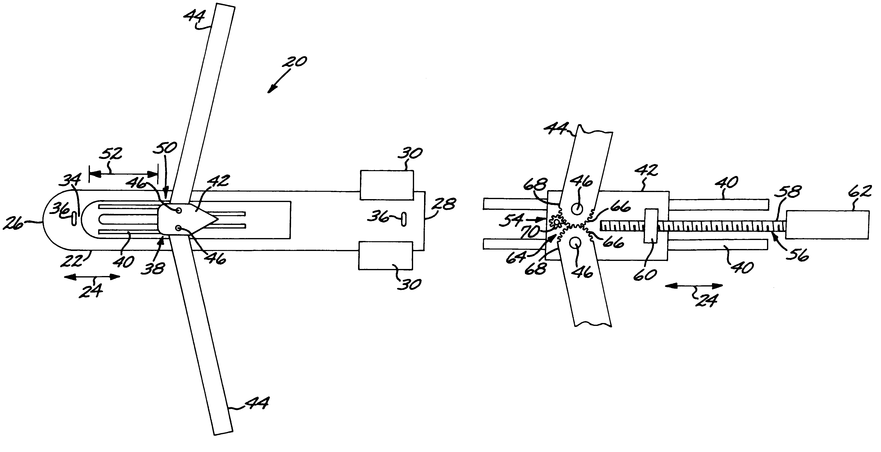
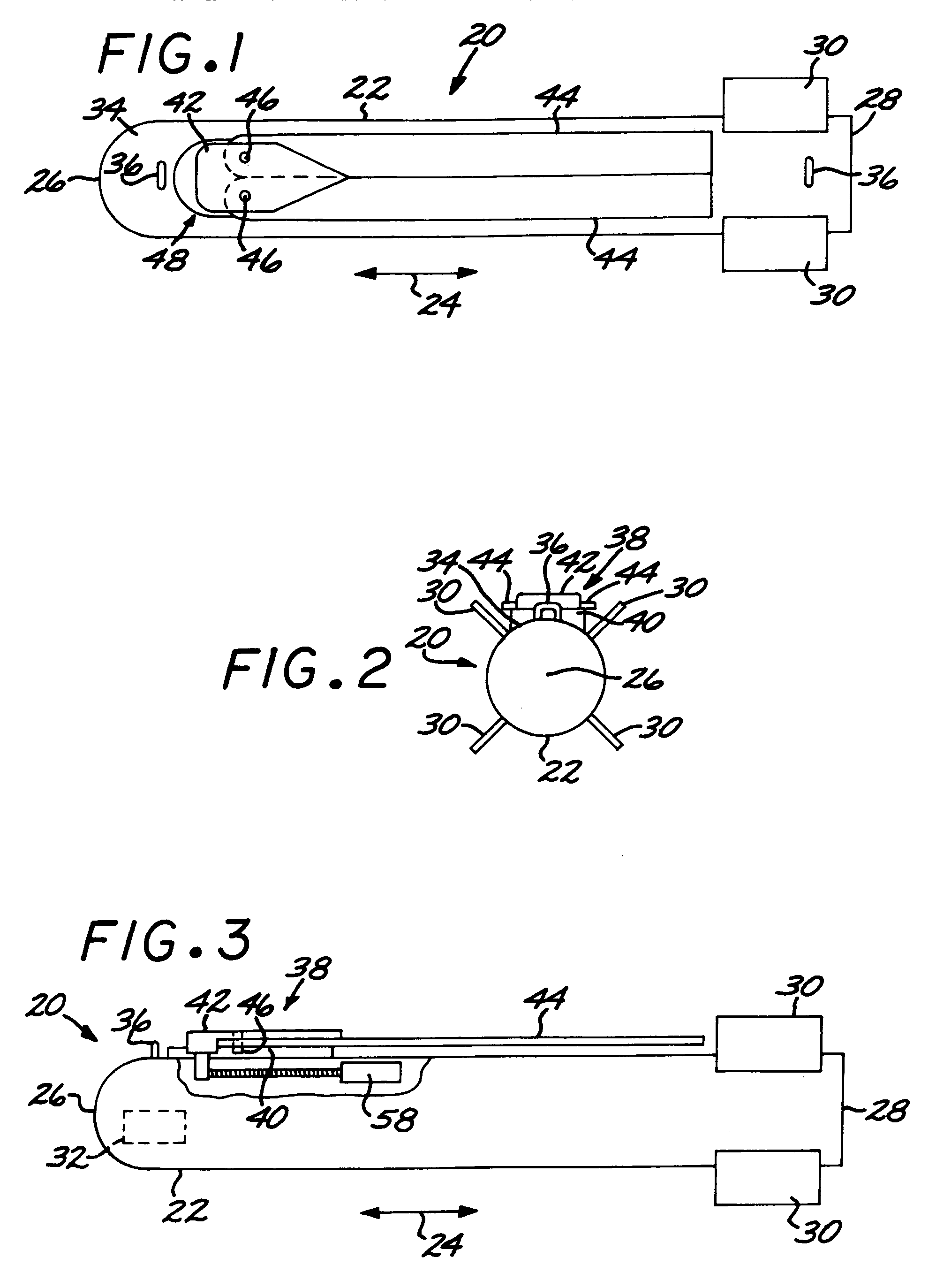
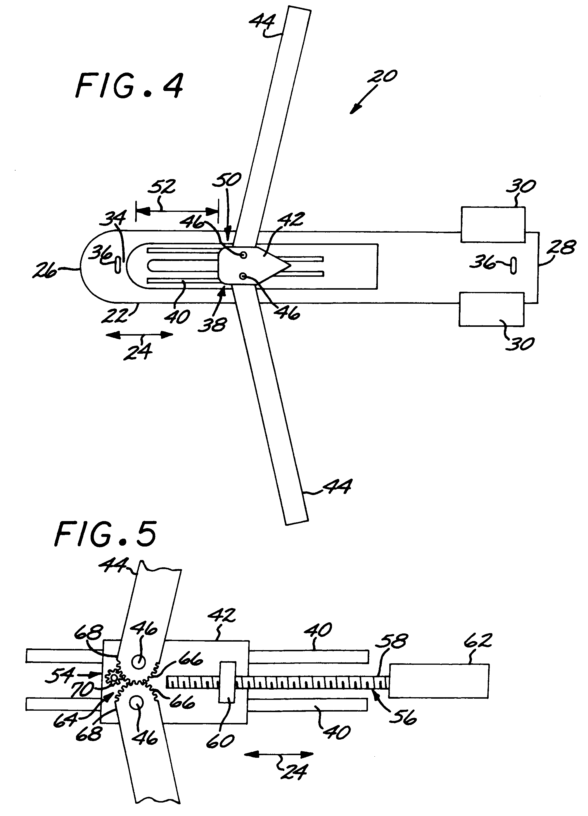
[0024]FIGS. 1–4 depict a winged vehicle 20 having an elongated fuselage 22 with a direction of elongation 24, a nose 26, and a tail 28. Extending from the fuselage 22 at a location near the tail 28 are four optional, but preferably present, movable guidance surfaces 30 extending outwardly from the fuselage. The optional movable guidance surfaces 30 are moved by actuators (not visible in the drawings) inside the fuselage 22 responsive to commands from an optional controller 32 that senses the position of the winged vehicle 20 in relation to its target and guides the winged vehicle 20 toward its target by movements of movements of the guidance surfaces 30. The controller 32 may optionally include other consistent features found in winged vehicles and known in the art, such as radar or infrared seekers, inertial or GPS guidance units, laser guidance units, transceivers, and communications uplinks and downlinks. A warhead (not visible in the drawings) typically occupies a major portion ...

second embodiment

[0035]FIG. 9 illustrates the winged vehicle 20, wherein elements common with the embodiments of FIGS. 1–6 are assigned the same reference numerals, and the prior discussion is incorporated. In the embodiment of FIG. 9, there is additionally a propulsion system 80. In this case, the propulsion system is in the form of a small solid rocket motor, but it may be a jet engine or other operable propulsion system. The winged vehicle 20 in this case may be a guided missile or a guided bomb that has a propulsive assist. A different drive motor configuration is used, with the drive motor being a pneumatic actuation mechanism with a cylinder and extendable drive piston that engages the wing-support body 42, and which as illustrated is positioned forward of the wing-support body 42. The nose 26 is also of a more aerodynamic shape than the generally hemispherical nose of FIGS. 1–4. These variations may be used singly or together, and in any operably combination with the features of the FIGS. 1–8...


PUM


Abstract

A winged vehicle includes an elongated fuselage, and a wing mechanism affixed to the fuselage. The wing mechanism has a wing-support-body track affixed to and extending lengthwise along the fuselage, a translating wing-support body engaged to and translatable along the wing-support-body track, and exactly two deployable cantilevered wings. Each deployable cantilevered wing has a wing pivot mounted to the translating wing-support body so that the deployable cantilevered wing is pivotable about the translating wing-support body. The two deployable cantilevered wings are each pivotable between a stowed position and a deployed position. An actuation mechanism is operable to controllably move the translating wing-support body along the wing-support-body track and to controllably move the two deployable cantilevered wings between the stowed position and the deployed position.

Description

[0001]This invention relates to a winged vehicle wherein the wings are initially stowed and then are deployed when the winged vehicle is launched and, more particularly, to the deployment mechanism.BACKGROUND OF THE INVENTION[0002]Until recently, most bombs were of the unguided, gravity type. The bomb was aimed by the motion of the aircraft on which it was carried and which flew approximately over the target. The bomb was released from a location on the flight path estimated to cause the bomb to fall onto its target. After the bomb was dropped there was no control over its motion. The result was that the aircraft was exposed to defensive measures over the target for an extended period of time in a flight path that was required to be straight and level, and the accuracy of the bombing was always somewhat problematic.[0003]Recent developments improved upon this type of earlier munition in important ways. Wings were affixed to the bomb so that it could be dropped at a distance from the...

Claims


Application Information

Patent Timeline
Patent Type & Authority Patents(United States)
IPC IPC(8): B64C3/40
CPCF42B10/12
Inventor BOUCHARD, MARK L.GOGINENI, PURNAEISENTRAUT, RUDOLPH A.PEREZ, JUAN A.GREENWOOD, KEVIN
Owner RAYTHEON CO
Why Eureka
Try Eureka