Plunger pump housing and access bore plug

a technology of plunger pump and housing, which is applied in the direction of pump components, positive displacement liquid engine, thin material handling, etc., can solve the problems of y-block design, plunger pump housing failure, and housing fatigue of plunger pump

Active Publication Date: 2007-03-06
HARRIS CORP
View PDF7 Cites 112 Cited by
  • Summary
  • Abstract
  • Description
  • Claims
  • Application Information

AI Technical Summary

Benefits of technology

[0026]Note also that the suction valve spring retainer mounting bracket and each suction valve spring retainer support comprises an inner surface, each inner surface generally conforming to a cylindrical envelope and being slightly spaced apart from the cylindrical envelope. The cylindrical envelope encompasses that space that would be cyclically occupied by a plunger during the plunger's (reciprocating) pumping movement in a plunger bore of the plunger pump housing in which the access bore plug may be secured. This spacing between inner surfaces and the cylindrical envelope allows the plunger's reciprocating (cyclic) motion to take place within the pump housing without interference due to striking a suction valve spring retainer mounting bracket or a suction valve spring retainer support arm.

Problems solved by technology

Plunger pump housings are subject to fatigue due to stresses resulting from alternating high and low pressures which occur with each stroke of the plunger cycle.
Plunger pump housings typically fail in areas of repetitive stress concentration.
Although several variations of the Y-block design have been evaluated, none have become commercially successful for several reasons.
One reason is that mechanics find field maintenance on Y-block fluid sections difficult.
For example, replacement of plungers and / or plunger packing is significantly more complicated in Y-block designs than in the earlier designs represented by FIG. 1.
This operation, which would leave the plunger packing easily accessible from the proximal end of the plunger bore, is impossible in a Y-block design.
Removing the gland nut, however, does not allow one to remove the packing rings.
This extraction, though, is not practical while a plunger piece lies within the packing box because of the excessive drag of the compressed packing rings on the plunger and packing box walls.
Such compression can not be released unless all plunger pieces are removed from the packing box because the packing rings in the above cartridge packing assemblies are pre-compressed when the assemblies are manufactured.
Further, any slight misalignment of apparatus used to extract such a cartridge packing assembly tends to cause binding of the (right cylindrical, i.e., not tapered) packing assembly within the (right cylindrical) bore in which it is installed.
Analogous difficulties occur if an attempt is made to replace such a cartridge packing assembly while a plunger or part thereof lies in the packing box area.
Hence, even if such cartridge packing assemblies were used in Y-block fluid section housings, multi-piece plungers would preferably be used and field maintenance would be correspondingly complicated and expensive.
Thus the Y-block configuration, while reducing stress in a plunger pump housing relative to earlier designs, is associated with significant disadvantages.
Unfortunately, designs incorporating secure placement of guides for both top and lower valve guide stems of suction valves have, before improvements described in the '706 application, been associated with complex components and difficult maintenance.

Method used


Image

  • Plunger pump housing and access bore plug
  • Plunger pump housing and access bore plug
  • Plunger pump housing and access bore plug

Examples


Embodiment Construction

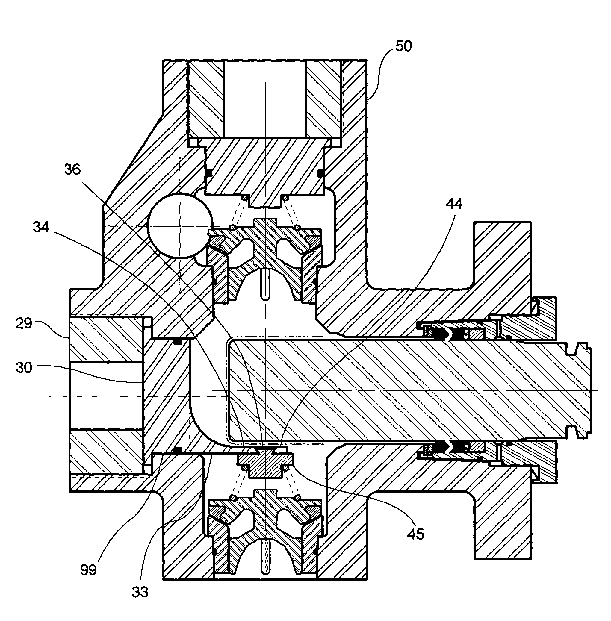
[0059]FIGS. 10A, 10B and 10C schematically illustrate three views of an access bore plug 30 of the present invention, intended for use in a plunger pump housing 50 having an offset access bore (as in, for example, FIG. 13). As seen in FIG. 10A, the elongated transverse cross-section of cylindrical portion 32 has a major axis (shown horizontal in FIG. 10A) and a perpendicular minor axis (shown vertical in FIG. 10A). Access bore plug features shown in FIGS. 10A, 10B and 10C include a flange 31 for securing the bore plug to plunger pump housing 50 using a threaded bore plug retainer 29 (see FIG. 13). A cylindrical portion 32 having a seal groove 132 extends longitudinally from flange 31, cylindrical portion 32 having an elongated transverse cross-section and extending longitudinally from said flange 31 sufficiently to slidingly and sealingly fit within a corresponding offset access bore cylindrical portion 99 in the plunger pump housing (see FIG. 13). Such a sliding and sealing fit wit...


PUM


Abstract

Suction valve spring retainers mounted using an access bore plug are described for use in plunger pump housings having an offset access bore and incorporating structural features for stress-relief. These pump housing structural features accommodate access bore plugs that secure suction valve spring retainers that are internally located substantially centrally over the suction bore transition area of the plunger pump housing. Access bore plugs are secured in place on the pump housing using one or more threaded retainers. Plunger pumps so constructed are relatively resistant to fatigue failure because of stress-reducing structural features, and they may incorporate a variety of valve styles, including top and lower stem-guided valves and crow-foot-guided valves, in easily-maintained configurations. Suction valve spring retainers mounted in plunger pump housings may also incorporate a suction valve top stem guide. Further, certain structural features of access bore plugs may be dimensioned to aid in improving volumetric efficiency of the pumps in which they are used.

Description

[0001]This is a continuation-in-part (CIP) of U.S. patent application Ser. No. 10 / 288,706, filed Nov. 6, 2002 now U.S. Pat. No. 6,623,259 as amended.FIELD OF THE INVENTION[0002]The invention relates generally to high-pressure plunger pumps used, for example, in oil field operations. More particularly, the invention relates to plunger pump housings that incorporate structural features for stress-relief and for accommodating valve spring retainers.BACKGROUND[0003]Engineers typically design high-pressure oil field plunger pumps in two sections; the (proximal) power section and the (distal) fluid section. The power section usually comprises a crankshaft, reduction gears, bearings, connecting rods, crossheads, crosshead extension rods, etc. Commonly used fluid sections usually comprise a plunger pump housing having a suction valve in a suction bore, a discharge valve in a discharge bore, an access bore, and a plunger in a plunger bore, plus high-pressure seals (including plunger packing)...

Claims


Application Information

Patent Timeline
Patent Type & Authority Patents(United States)
IPC IPC(8): F04B39/10F04B53/00F04B53/10F04B53/16
CPCF04B53/007F04B53/164F04B53/16F04B53/1032Y10T137/7838Y10T137/7939
Inventor BLUME, GEORGE H.
Owner HARRIS CORP
Why Eureka
Try Eureka