Means and Method for Electrically Connecting Photovoltaic Cells in a Solar Module

a solar module and photovoltaic cell technology, applied in photovoltaic supports, climate sustainability, sustainable buildings, etc., can solve the problems of more connections, failure of connections, and end of expected useful life of solar modules, so as to reduce stress failures in the ribbon

Inactive Publication Date: 2007-06-28
BP CORP NORTH AMERICA INC
View PDF5 Cites 54 Cited by
  • Summary
  • Abstract
  • Description
  • Claims
  • Application Information

AI Technical Summary

Benefits of technology

[0008] The present invention provides a means and method for electrically connecting adjacent PV cells together in a solar module. Basically, the terminals of adjacent cells are connected together using individual lengths of an electrically conductive material; e.g. lengths of ribbons made of copper or the like which are typically coated with solder. A substantial portion of the mid section of electrically conductive material, such as the ribbons, remains unsoldered to thereby provide a stress relief zone in the electrically conductive material between the cells to alleviate stress failures in the ribbons. The PV cells can be, and preferably are, of the type made from semiconductor wafers, such as silicon wafers. The silicon wafers can be made from mono-crystalline or multi-crystalline silicon. These PV cells can be any shape, but are typically circular, square, rectangular or pseudo-square in shape. By “pseudo-square” is meant a predominantly square shape usually with rounded corners. For example, a mono-crystalline or multi-crystalline PV cell useful in this invention can be about 50 microns thick to about 400 microns thick. If circular, it can have a diameter of about 100 to about 200 millimeters. If rectangular, square or pseudo square, it can have sides of about 100 millimeters to about 210 millimeters and where, for the pseudo-square wafers, the rounded corners can have a diameter of about 127 to about 178 millimeters. Such wafers and cells and methods for making them are known in the art.

Problems solved by technology

While these connections appear to work well over relatively long periods, it has been found that some of these connections may fail before the expected useful life of the solar modules has ended.
It appears that a major reason that one or more of these connections may fail results from the stress which is experienced by the short length of the ribbon between the cells as it expands and contracts caused by the cyclic changes in temperature over the operational life of the module.
This stress fatigues the ribbon and causes it to break much like the continuous flexing of a wire leads to the wire breaking at the point of flexure and can cause failure of the solder joint, itself.
Since the solar modules are sealed units, the failure of only one of these connections between PV cells (which are usually connected in series) can render a module inoperable and require replacement long before its otherwise useful life is over.
Due to the costs involved, this can seriously detract from the commercialization of solar power.

Method used


Image

  • Means and Method for Electrically Connecting Photovoltaic Cells in a Solar Module
  • Means and Method for Electrically Connecting Photovoltaic Cells in a Solar Module
  • Means and Method for Electrically Connecting Photovoltaic Cells in a Solar Module

Examples


Embodiment Construction

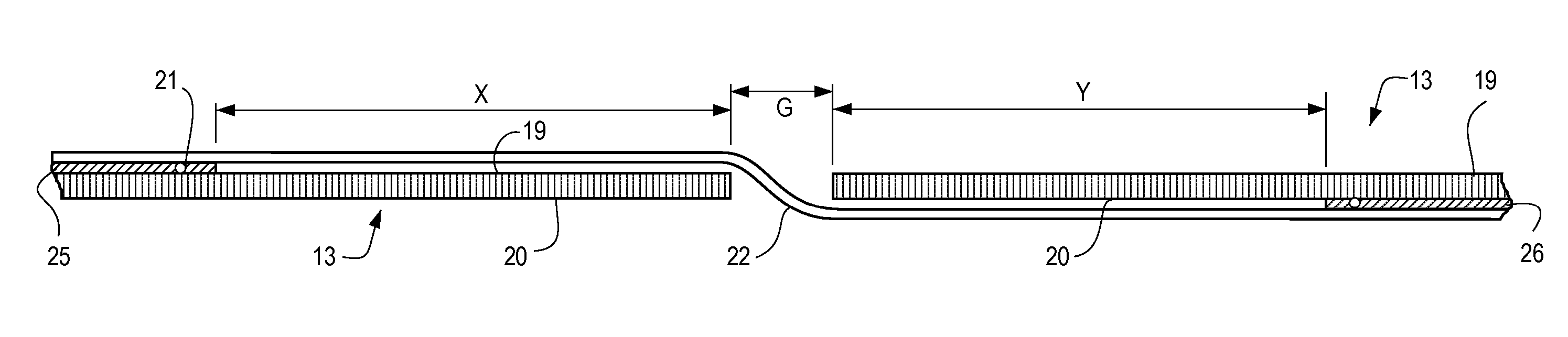
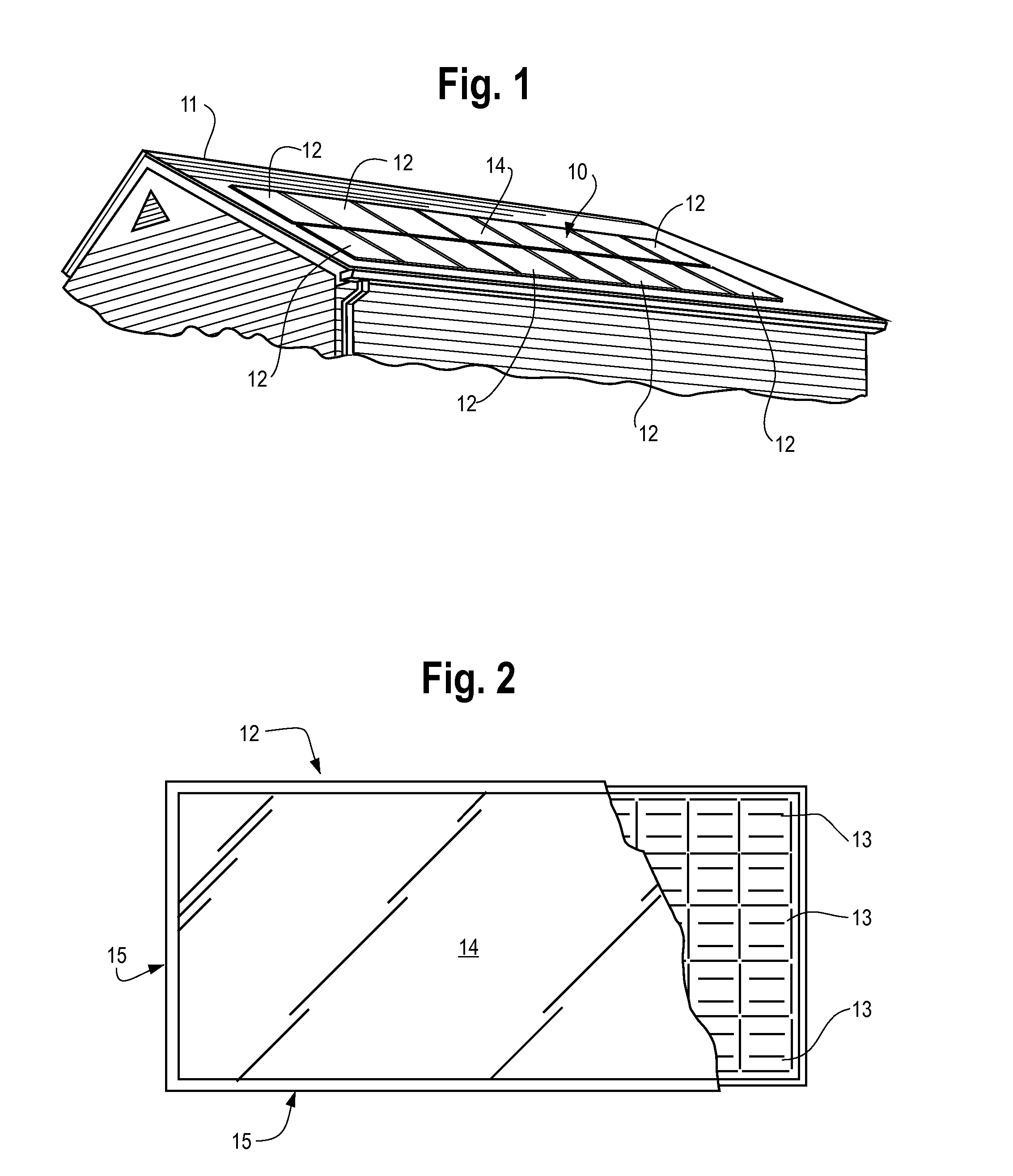
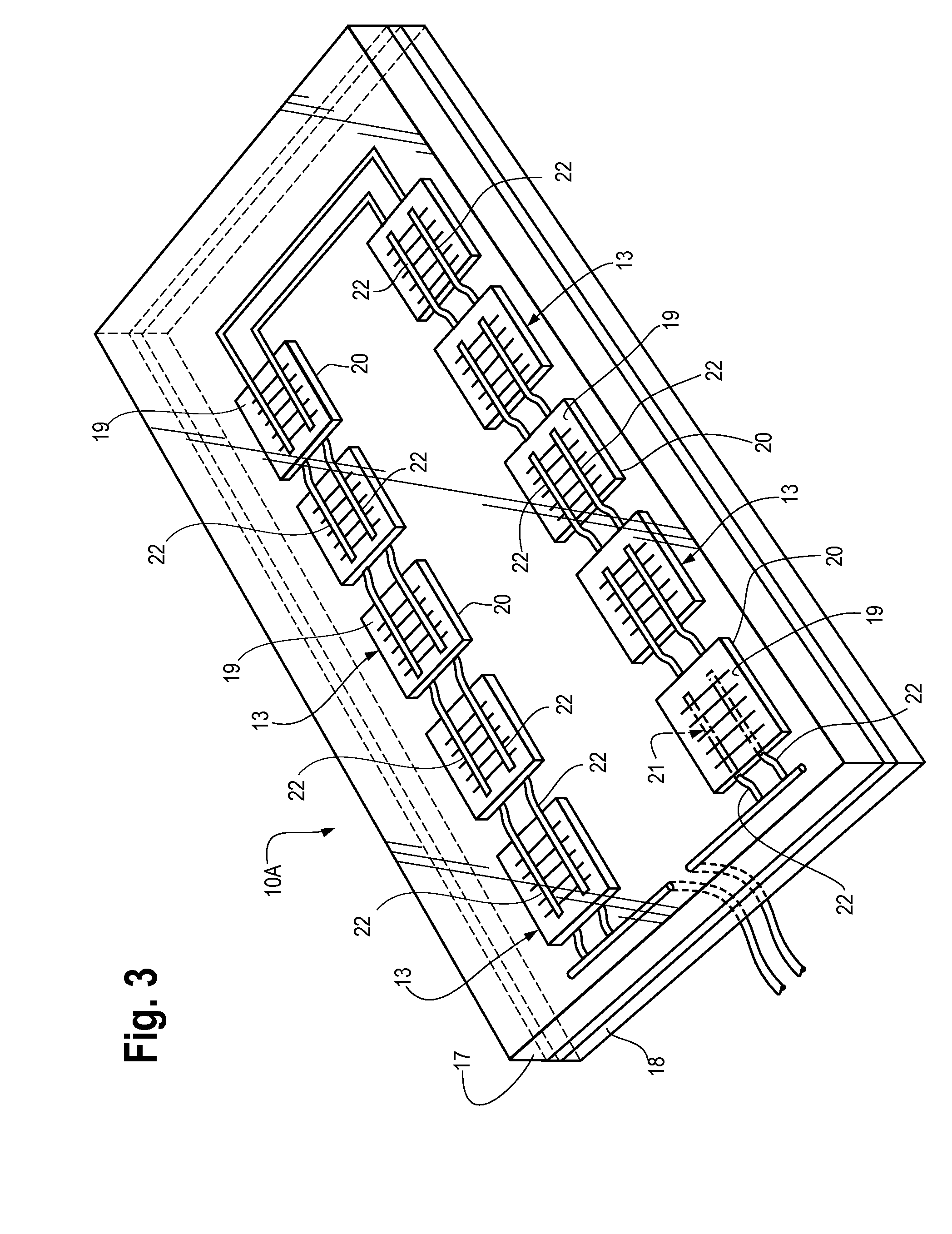
[0019] Referring now to the drawings, FIG. 1 illustrates a typical solar array 10 incorporating the present invention which has been mounted on a support surface (e.g. roof 11 of a house or the like). Array 10 is comprised of a plurality (sixteen shown) of solar modules 12 (only some numbered) which have been secured to the roof 11 as shown. As will be fully understood in the art, a typical solar module 12 is basically formed by positioning a plurality of photovoltaic (PV) cells 13 (FIG. 2) between a sheet of a transparent material 14 (e.g. glass, plastic, etc.) and another sheet of material (not shown), whereby the finished module 12 is effectively a flat, rectangular, plate-like structure as shown in the figures.

[0020] To complete the assembly of module 12, the sandwich of PV cells 13 is typically encased within a frame 15. Typical measurements of a solar cell module 12 of this type is approximately thirty-one (31) inches wide and sixty-three (63) inches long. A suitable frame fo...


PUM


Abstract

A connector and method for electrically connecting adjacent solar cells together in a solar module. The terminals of the cells are connected with individual lengths of an electrically conductive material such as an electrically conductive metal ribbon. A substantial portion of the mid section of the ribbons remain unsoldered to thereby provide a stress relief zone in the ribbon between the cells to alleviate stress failures in the ribbons.

Description

[0001] This application claims the benefit of U.S. Provisional Patent Application 60 / 741,916 filed on Dec. 2, 2005, and 60 / 758,519 filed on Jan. 12, 2006.FIELD OF THE INVENTION [0002] The present invention relates to electrically connecting photovoltaic (PV) cells within a solar module and in one of its aspects relates to a means and method for electrically connecting a plurality of PV cells in a solar module to effectively extend the operational life of the connections between PV cells. BACKGROUND OF THE INVENTION [0003] In recent years, considerable advances have been made in photovoltaic cells or the like for directly converting solar energy into useful electrical energy. Typically, a plurality of these photovoltaic cells are encased between a transparent sheet (e.g. glass, plastic, etc.) and a sheet of backing material to thereby form a flat, rectangular-shaped module (sometimes also called “laminate” or “panel”) of a manageable size (e.g. 2½′×5′). This is the type of solar modu...

Claims


Application Information

Patent Timeline
Patent Type & Authority Applications(United States)
IPC IPC(8): H01L31/00
CPCY02E10/50H02S20/23Y02B10/12H01L31/0504H01L31/048Y02B10/10H01L31/05
Inventor CUNNINGHAM, DANIEL W.CREAGER, JOSEPH B.WOHLGEMUTH, JOHN H.
Owner BP CORP NORTH AMERICA INC
Why Eureka
Try Eureka