Mesh graft and stent for increased flexibility

Inactive Publication Date: 2007-03-06
LIFEPORT SCI
View PDF38 Cites 71 Cited by
  • Summary
  • Abstract
  • Description
  • Claims
  • Application Information

AI Technical Summary

Benefits of technology

[0012]It is therefore an object of the present invention to provide an endoluminal prosth

Problems solved by technology

However, as the graft covers the stent, it has a tendency to reduce the longitudinal flexibility of the composite device.
A reduction in longitudinal flexibility makes intralumin

Method used


Image

  • Mesh graft and stent for increased flexibility
  • Mesh graft and stent for increased flexibility
  • Mesh graft and stent for increased flexibility

Examples


Example

[0024]The following is a detailed description of the preferred embodiments of the present invention. The description is meant to describe the preferred embodiments, and is not meant to limit the invention in any way.

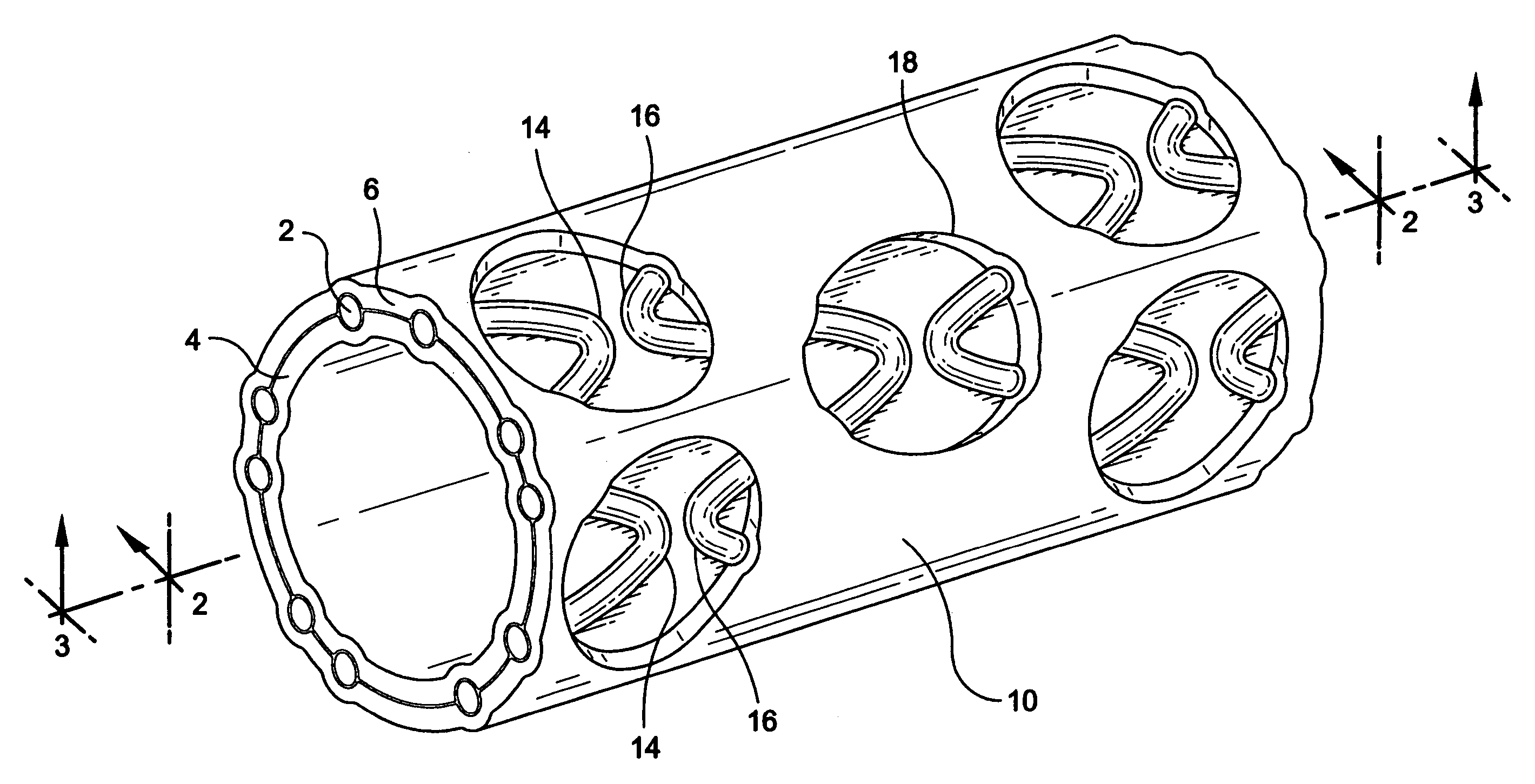
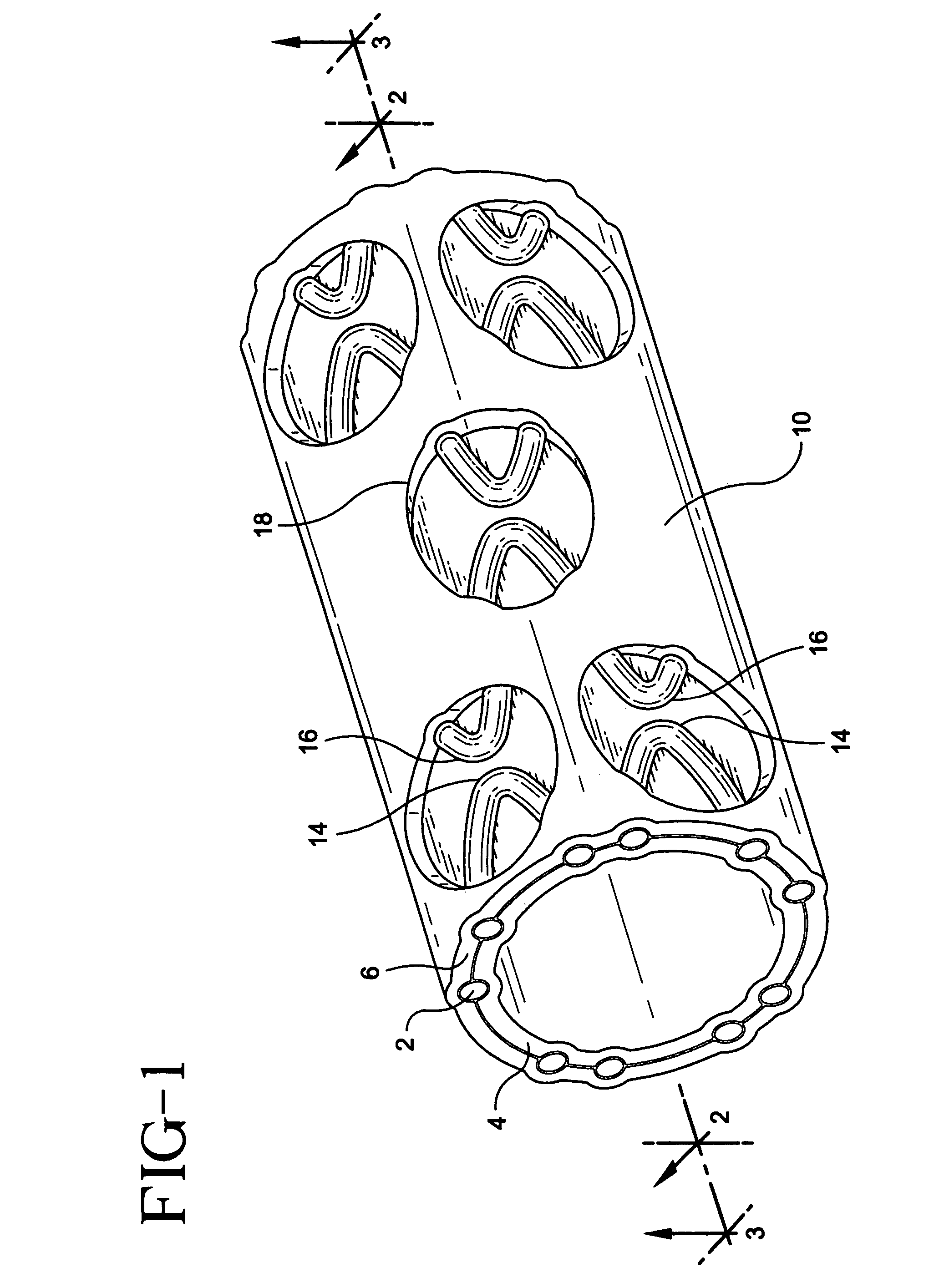
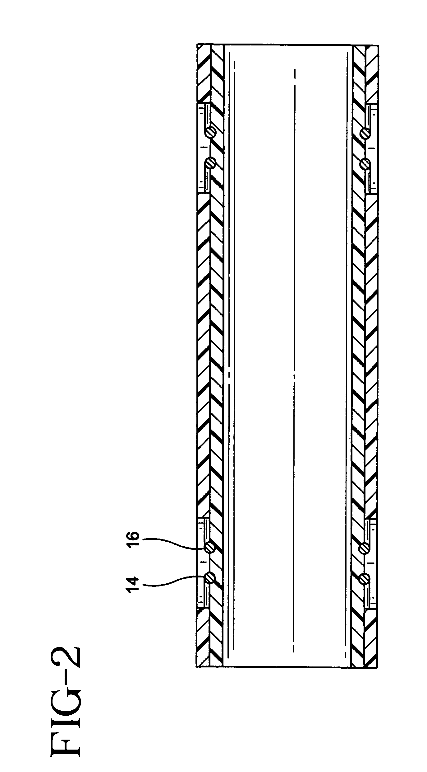
[0025]A stent / graft prosthesis 10 of the present invention is shown in FIG. 1. The prosthesis includes a stent 2, an inner tubular layer 4, and an outer tubular layer 6. The stent is positioned between the inner and outer tubular layers.

[0026]The stent in the present invention is formed from an elongate wire 12 which is helically wound with a plurality of longitudinally spaced turns into an open tubular configuration. As partially shown in FIG. 6, a stent 2 is of the type which is particularly suited for use in the endoluminal prosthesis of the present invention. The stent 2 is an expandable tubular member which may be either of the balloon-expanded or self-expanded type. Stents of this type are typically introduced intraluminally into the body, and expanded at the impla...


PUM


Abstract

A composite stent-graft tubular prosthesis includes an inner PTFE tubular structure, an outer PTFE tubular structure positioned about the inner PTFE tubular structure and a diametrically deformable stent interposed between the inner and outer PTFE tubular structures. The interposed stent is formed from an elongate wire helically wound with a plurality of longitudinally spaced turns into an open configuration. Each of the turns includes successive aligned upper and lower wave-like peaks. Selective ones of said upper and lower peaks are exposed exteriorly of the outer PTFE structure to render the composite prosthesis longitudinally flexible.

Description

CROSS REFERENCE TO RELATED APPLICATION[0001]This application is a continuation of and claims priority to Ser. No. 10 / 716,639, filed Nov. 19, 2003, which is a continuation of Ser. No. 09 / 571,530 filed May 16, 2000 now U.S. Pat. No. 6,673,103, the contents of which are incorporated herein by reference.FIELD OF THE INVENTION[0002]The present invention relates generally to an implantable prosthesis used to repair or replace a body lumen. More particularly, the present invention relates to an endoluminal prosthesis including a stent and ePTFE graft composite device offering increased compliance and flexibility.BACKGROUND OF THE INVENTION[0003]An endoluminal prosthesis is a medical device commonly known to be used in the treatment of diseased blood vessels. An endoluminal prosthesis is typically used to repair, replace, or otherwise correct a damaged blood vessel. An artery or vein may be diseased in a variety of different ways. The prosthesis may therefore be used to prevent or treat a w...

Claims


Application Information

Patent Timeline
IPC IPC(8): A61F2/06A61F2/00
CPCA61F2/07A61F2/89A61F2250/0029A61F2002/072
Inventor GOLDS, ELLENTSENG, DAVIDBOATMAN, JEFF
Owner LIFEPORT SCI
Why Eureka
Try Eureka