Mounting bracket for a security device

a security device and mounting bracket technology, applied in the direction of magnetic/electric field switches, contact mechanisms, electrical apparatus, etc., can solve the problem of increasing the distance between the first and second switch elements, and achieve the effect of reducing reluctance and increasing the strength of the applied magnetic field

Inactive Publication Date: 2007-03-06
HARCO LAB
View PDF19 Cites 16 Cited by
  • Summary
  • Abstract
  • Description
  • Claims
  • Application Information

AI Technical Summary

Benefits of technology

[0021]It is understood that over time, the first member may move relative to the second member. For example, when the first and second members comprise a door and door jam, over time the door may sag. This sagging of the door relative to the frame disadvantageously causes the distance between the first and second switch elements to increase. Accordingly, in another advantageous embodiment, a mounting bracket is provided that allows for variable adjustment of the distance between the first and second switch elements.
[0039]In yet another advantageous embodiment, a magnetic switching system for detecting relative movement between a first and a second member is provided. The switch device comprises a first part coupled to the first member including a switch having an electrically conductive shiftable body that shifts between simultaneous contact with two switch elements and non-simultaneous contact with the two switch elements based upon an applied magnetic field. The first part includes a flux concentrator positioned in proximity with the shiftable body, the flux concentrator providing a reduced reluctance path for the applied magnetic field such that the strength of the applied magnetic field is increased and the flux concentrator directing at least a portion of a magnetic field emanating therefrom toward the switch. The switch device further comprises a second part coupled to the second member including a magnetic component to generate the applied magnetic field, the first and second parts spaced apart from each other by an operational gap. The switch device still further comprises a bracket affixed to the first member, the bracket having a substantially flat body including a mounting element receiving the first part thereon, the bracket further including two substantially parallel slots extending through the substantially flat body, the slots extending perpendicular to the operational gap such that the size of the operational gap may be adjusted.

Problems solved by technology

This sagging of the door relative to the frame disadvantageously causes the distance between the first and second switch elements to increase.

Method used


Image

  • Mounting bracket for a security device
  • Mounting bracket for a security device
  • Mounting bracket for a security device

Examples


Embodiment Construction

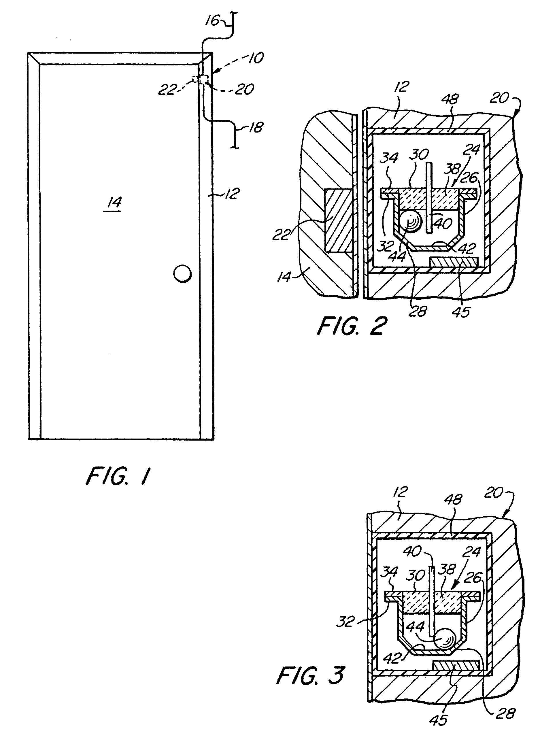
[0064]Turning now to the drawings, FIG. 1 illustrates a magnetic switch 10 (dashed lines) shown used with a doorframe 12 and door 14. Electrical leads 16, 18 are operatively coupled with the switch 10. While FIG. 2 illustrates a contact that is normally open when the door is in the secure position, it is contemplated that a normally closed contact when the door is in the secure position is equally applicable.

[0065]The switch 10 includes a switch assembly 20 secured to frame 12, as well as a second attractive component 22, which is mounted to door 14. The switch assembly 20 may include a housing 24 having a circumscribing annular sidewall 26, an integral concavo-convex bottom wall 28 and a top cover 30. Preferably, the integral sidewall and bottom wall 26, 28 presents a circumscribing flange 32 and is formed of a suitable non-magnetic, electrically conductive material, such as for instance, cupro-nickel alloy. The top cover 30 includes an outboard flange 34 adapted to mate with flang...


PUM


Abstract

A universal magnetic switching assembly for detecting relative movement between first and second members, the universal switching assembly mounted on a bracket that may be used to adjust the positioning of the magnetic components relative to each other on opposing members to maintain the operational gap between the opposing magnetic components.

Description

CROSS-REFERENCE TO RELATED APPLICATIONS[0001]This application is a continuation in part of U.S. patent application Ser. No. 11 / 317,117 filed Dec. 22, 2005, which is a continuation in part of U.S. patent application Ser. No. 11 / 203,497 filed Aug. 12, 2005.FIELD OF THE INVENTION[0002]The present invention is directed toward a mounting bracket that may be used in connection with magnetic switches used as part of alarm systems to detect relative movement between a first and a second member such as a door and doorframe. More specifically, the present invention provides an improved mounting bracket, which may be used to adjust the relative positioning of the magnetic components.BACKGROUND OF THE INVENTION[0003]Security alarm systems often use magnetic switches attached to doors and windows for detecting unauthorized openings. One type of magnetic switch utilized is a reed switch. However, these switches are subject to unauthorized manipulation through use of, for example, an external magn...

Claims


Application Information

Patent Timeline
Patent Type & Authority Patents(United States)
IPC IPC(8): H01H9/00
CPCH01H9/0207H01H36/0033H01H36/0046H01H2036/0086H01H2003/165
Inventor HABBOOSH, SAMIR W.
Owner HARCO LAB
Why Eureka
Try Eureka