Automatic flicker frequency detection device and method

Active Publication Date: 2007-03-06
PIXART IMAGING INC
View PDF8 Cites 45 Cited by
  • Summary
  • Abstract
  • Description
  • Claims
  • Application Information

AI Technical Summary

Benefits of technology

[0014]In either of the first two embodiments, the approach to detecting the specific repeating patterns (e.g., fluorescent lighting fluctuations that are determined by the AC waveform of the power source) operates well for images having large areas of image uniformity. For example, if a significant portion or all of the image is a single shade of gray, flicker is readily detected using either approach. However, flicker is more difficult to identify within an image having constant unpredictable variations, such as a captured image of a fluorescent-illuminated portrait of a rock-cluttered mountainside. Within such an image, the desirable image signal may be stronger than the flicker artifact by two or three orders of magnitude. As another complication, some of the desired signal energy has the same spatial frequency as the 100 / 120 Hz artifacts. Therefore, in a third embodiment of the invention, the row average signal described with reference to the second embodiment is obtained for each of two frames, preferably successive frames. The columnar information of the third embodiment is computed by determining the difference between the corresponding row values for the two row average signals. The columnar information may therefore be considered a difference signal. The difference signal is then analyzed to detect the artifact. This process operates well, since the flicker artifact tends to move from one frame to the next, while the objects within the image exhibit little or no movement. Therefore, most of the desired signal energy in the frames is removed in the process of forming the difference signal (i.e., the columnar information). The difference signal will be composed largely of the energy from the flicker artifact, if flicker is present in the image. Optionally, the frame rate of the imaging device can be varied slightly during the flicker detection process, thereby ensuring that the artifact does shift from one frame to the next frame.
[0017]In one approach, a cross-correlation is performed between the columnar information and separate sinusoidal basis functions centered at 100 Hz and 120 Hz. This technique is particularly effective if the cross-correlation is done over an interval of 0.05 seconds (or an integer multiple of 0.05 seconds), since the two basis functions will be perfectly orthogonal. If the sinusoidal basis functions are generated in quadrature, it is possible to detect the phase of the artifact signal. Detecting the phase is useful, since the artifact tends to roll up or down through an imaged scene at a fixed rate. By knowing in advance how the position of the artifact changes from one frame to the next, the detection may be made more robust in the presence of non-flicker signal energy and movement of objects within the images.

Problems solved by technology

However, flicker is more difficult to identify within an image having constant unpredictable variations, such as a captured image of a fluorescent-illuminated portrait of a rock-cluttered mountainside.

Method used


Image

  • Automatic flicker frequency detection device and method
  • Automatic flicker frequency detection device and method
  • Automatic flicker frequency detection device and method

Examples


Embodiment Construction

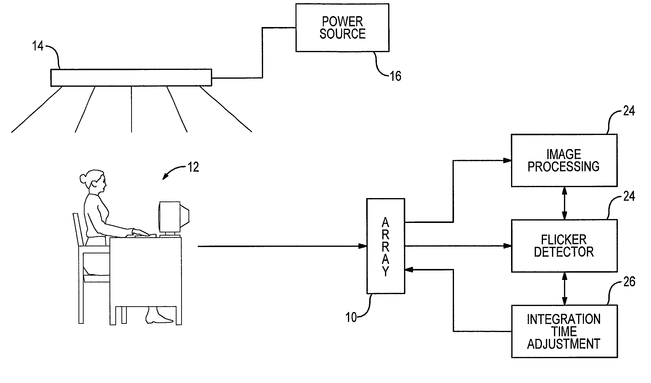
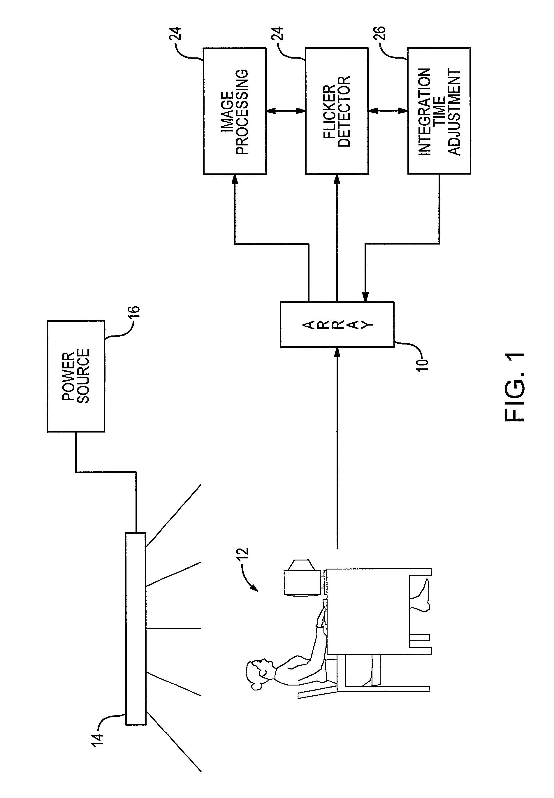
[0025]With reference to FIG. 1, a two-dimensional array 10 of sensors is shown as being positioned to generate image information of a scene 12 that includes a person seated at a desk. The scene is shown as being illuminated by a fluorescent lighting system 14 connected to a power source 16. As is known in the art, the lighting system is subject to periodic fluctuations in illumination intensity. For example, if the power source has an output of a 60 Hz waveform, the fluorescent lighting system will have intensity peaks of 120 Hz. On the other hand, if the output of the power source is a 50 Hz waveform, the intensity peaks of the lighting system will be 100 Hz. While the invention will be described with reference to use of a fluorescent lighting system, the techniques may be used with other lighting systems that exhibit periodic intensity variations.

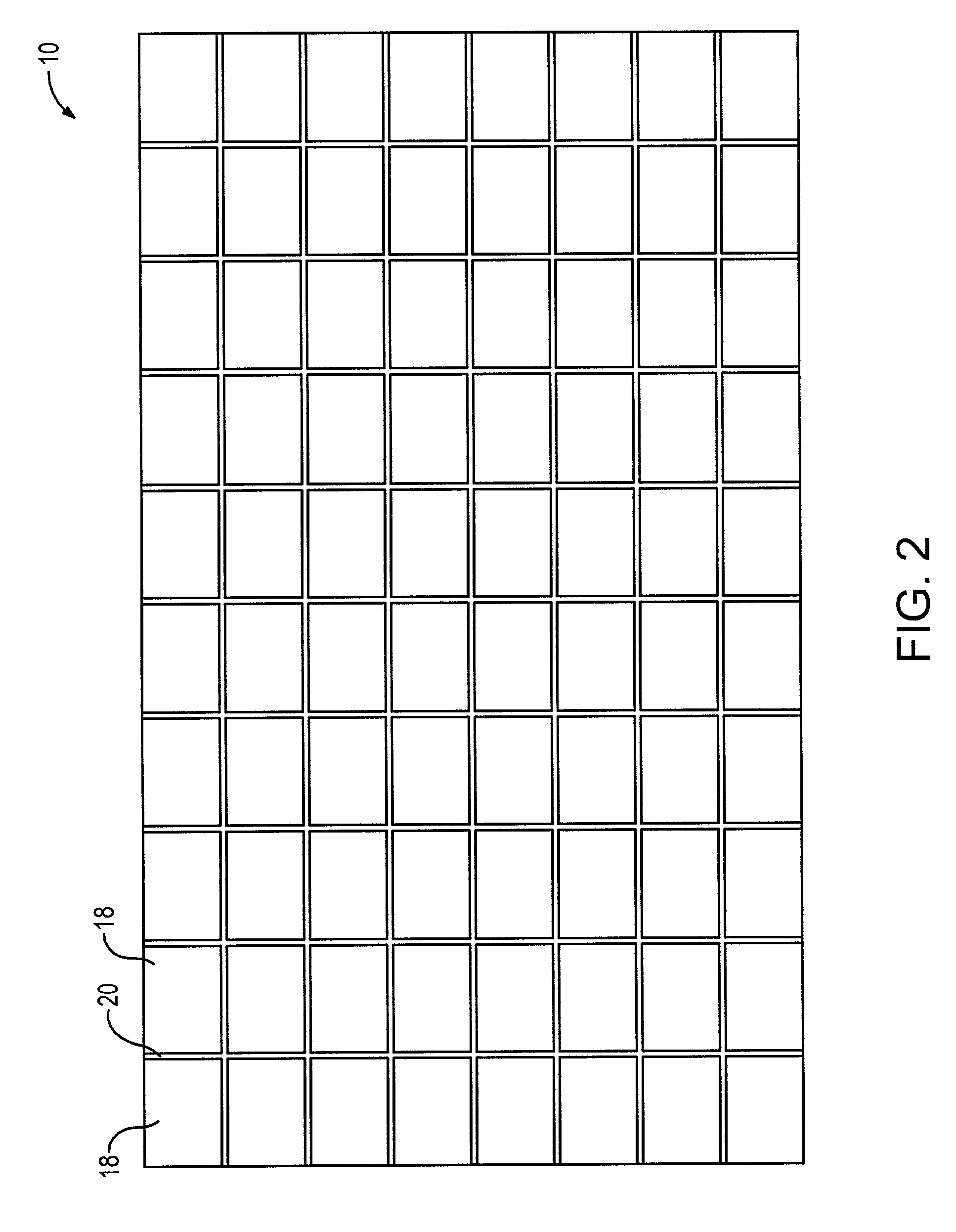
[0026]An example of the two-dimensional array 10 is shown in FIG. 2. The array may be of the type used in commercially available digital...


PUM


Abstract

An image device, such as a digital camera, detects specific repeating patterns of signal variations by processing columnar information from the device's two-dimensional sensor array used to generate images. In one embodiment, the columnar information is derived from calculating row averages for two image frames, with each row average being a computed average of the multiple signal intensities generated from some or all of the sensors within a particular row. After the columnar information is determined for each of the two frames, a difference signal is generated as a sequence of the differences between the row averages for the first frame and the row averages for the second frame. This row averaging and frame differencing removes a large percentage of the signal energy that is not a result of the artifact of interest, such as the flicker generated by illumination having intensity fluctuations at 100 Hz or at 120 Hz. In some embodiments of the invention, the row averaging and / or the frame-to-frame comparison are deleted.

Description

TECHNICAL FIELD[0001]The invention relates generally to devices and methods which provide automatic detection of flicker and more particularly to devices and methods which enable discrimination between periodic lighting fluctuations of different frequencies.BACKGROUND ART[0002]One approach to capturing images is to provide an array of solid state sensors that generate output signals in response to the intensity of light received at the individual sensors over a particular integration time. Thus, the sensors convert photon energy into electrical energy. As one possibility, the sensors may be CMOS image sensors that are arranged in a two-dimensional array to generate image information for display or storage.[0003]A concern is that imaging devices that do not instantaneously capture all of the image information used to form a frame are susceptible to introduction of an image artifact referred to as “flicker.” When an imaged scene is illuminated by a fluorescent light source, light inte...

Claims


Application Information

Patent Timeline
IPC IPC(8): H04N9/73H04N5/235
CPCH04N5/2357H04N5/235H04N23/745H04N23/70
Inventor POPLIN, DWIGHTZELMAN, MICHAEL J.CLARK, II, AIRELL R.SACHS, TODD S.
Owner PIXART IMAGING INC
Why Eureka
Try Eureka