Split pole spoke type PM machine with enclosed magnets

a technology of enclosed magnets and spokes, which is applied in the direction of dynamo-electric machines, magnetic circuit rotating parts, and shape/form/construction of magnetic circuits, etc., can solve the problems of waste of assembly costs, and achieve the effects of high speed operation, simple and inexpensive, and high performan

Active Publication Date: 2017-08-15
GM GLOBAL TECH OPERATIONS LLC
View PDF2 Cites 0 Cited by
  • Summary
  • Abstract
  • Description
  • Claims
  • Application Information

AI Technical Summary

Benefits of technology

[0005]An advantage of the invention described is the spoke-type lamination rotor design which simultaneously achieves high performance with a simple and inexpensive rotor core structure for high speed operation. The rotor core structure utilizing a plurality of single laminations which reduces parts count and simplifies the mechanical structure and reduces cost for high speed operation comparing to conventional spoke-type motors where the rotor lamination is a multi-piece construction utilizing pins and end caps to hold the together the rotor structure. The simple magnet shape allows for fewer magnet pieces compared to those motors used in permanent magnet synchronous reluctance (PMA SynRel) machines which can use from two to eight or more magnets per pole and have unconventional shaped magnets. Moreover, at least one pair of split pair magnets may be used pole which allows magnets to be made more robust while still offering the desired magnetic properties as seen in the PMA SynRel machines. Moreover, utilizing a conventional shape and sized magnet reduces assembly cost waste particularly in regards to scrap costs from broken magnets during assembly due to complex and non-robust shapes of the magnets.
[0006]An embodiment contemplates a rotor for a permanent magnet synchronous machine including a rotor core structure. A first set of permanent magnets forms respective poles within the rotor core structure. Each pole includes a pair of permanent magnets from the first set of permanent magnets. A first set of apertures is formed in a first radial layer of the rotor core structure. The first set of permanent magnets is inserted with the first set of apertures. Each pole includes a pair of apertures from the first set of apertures. The respective apertures within a respective pole are spaced a first circumferential distance apart. A second set of apertures is formed in a second radial layer of the rotor core structure. Each pole includes a pair of apertures from the second set of apertures. The second set of apertures is formed radially inward from the first set of apertures. A third set of apertures is formed in a third radial layer of the rotor core structure. The third set of apertures is formed radially outward from the first set of apertures. A second set of permanent magnets is inserted within the third set of apertures. The second set of permanent magnets have a different magnetic field strength relative to the first set of permanent magnets. Each pole includes a pair of permanent magnets from the first set of permanent magnets and a pair of permanent magnets from the second set of permanent magnets cooperatively generating a magnetic field in a same direction. The permanent magnets in the first and second layers of a respective pole generates the magnetic field in a direction opposite to a magnetic field generated by the permanent magnets in the first and second layers of an adjacent pole.

Problems solved by technology

Moreover, utilizing a conventional shape and sized magnet reduces assembly cost waste particularly in regards to scrap costs from broken magnets during assembly due to complex and non-robust shapes of the magnets.

Method used


Image

  • Split pole spoke type PM machine with enclosed magnets
  • Split pole spoke type PM machine with enclosed magnets
  • Split pole spoke type PM machine with enclosed magnets

Examples


Embodiment Construction

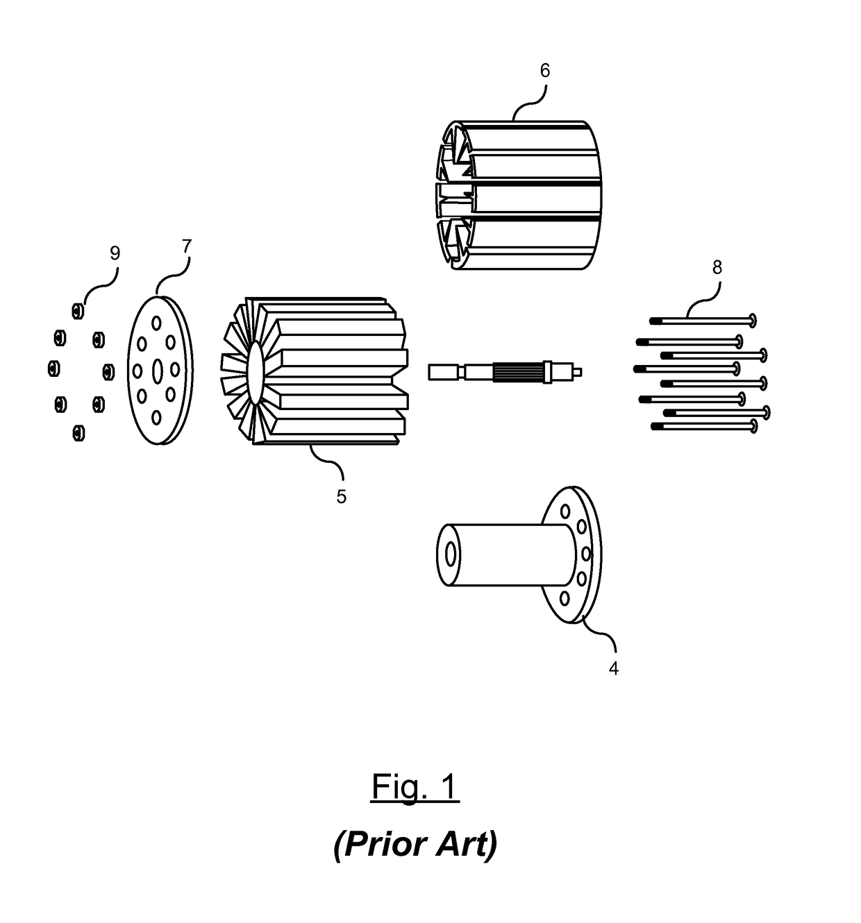
[0012]FIG. 1 illustrates an expanded view of a conventional rotor used in an electric motor synchronous machine as is known in the art. The conventional spoke-type rotor is a multi-piece rotor. The rotor includes a bobbin 4 with an integrated endcap on a first end of the bobbin 4. A plurality of individual magnets 5 is assembled into a like number of laminated steel pole assemblies 6 to form a rotor magnet / core assembly. The laminated steel pole assemblies 6 include disconnected individual steel pole pieces spaced between each set of adjacent magnets. The magnet / core assembly is inserted onto the bobbin 4. A second endcap 7 is coupled to the second end of the bobbin 4 and is secured together using a plurality of pins 8 that extend through the endcaps and the magnet / core assembly 6. The pins 8 are secured using fasteners 9. As a result, the conventional spoke-type motor is a multi-piece rotor structure requiring a plurality of parts for assembly.

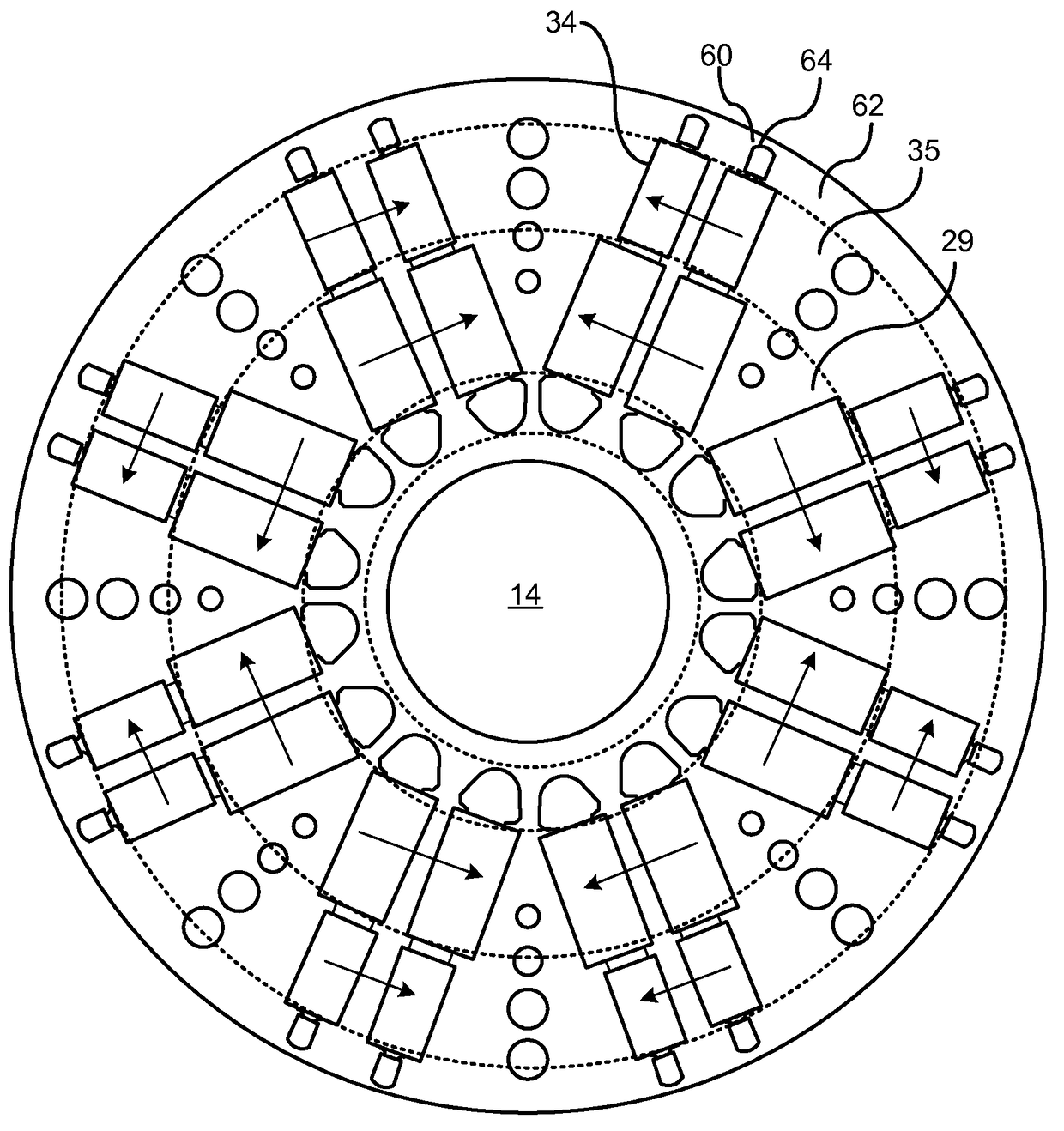
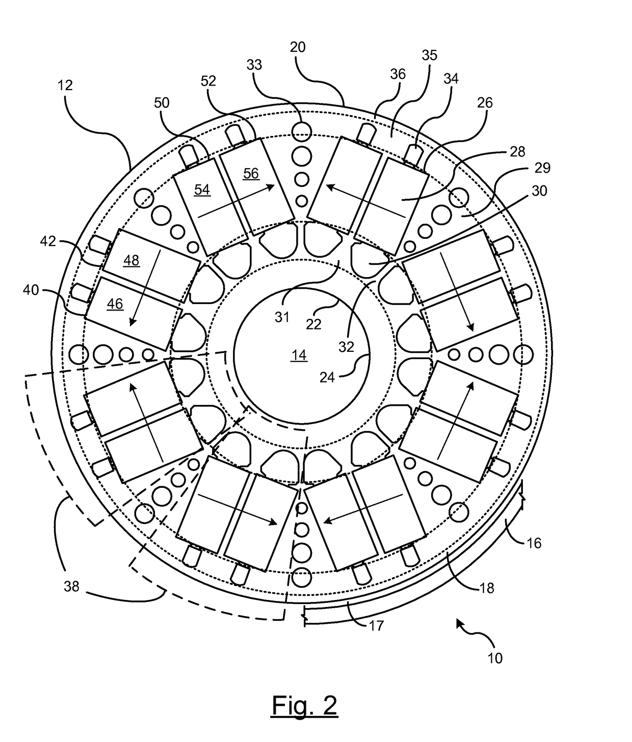
[0013]There is shown in FIG. 2 a secti...


PUM


Abstract

A rotor for a permanent magnet synchronous machine that includes a rotor core structure. A first set of permanent magnets forms poles within the rotor core structure. Each pole includes a pair of permanent magnets from the first set of permanent magnets. A first set of apertures is formed in a first radial layer of the rotor core structure. Each pole includes a pair of apertures from the first set of apertures. The first set of permanent magnets is inserted within the first set of apertures. Each pair of permanent magnets within a pole cooperatively generates a magnetic field in a same direction within the pole. The magnetic field generated by a respective pair of magnets in a respective pole is opposite to a magnetic field generated by a pair of permanent magnets in an adjacent pole.

Description

BACKGROUND OF INVENTION[0001]An embodiment relates generally to permanent magnet motors.[0002]A permanent magnet synchronous motor is an AC motor in which the rotation rate of the shaft is synchronized with the frequency of the AC supply current. A rotating electric field is generated in the stator and the rotor follows the rotating electrical field of the stator. The rotor rotates in step with the field of the stator at a same rate. The rotor and the stator are said to be in synchronization.[0003]The permanent magnets used in conventional rotors are configured to provide a specified alternating magnetic field distribution in the air gap. In an effort to reduce the amount of rare-earth magnets, some machines utilize a permanent magnet assist synchronous reluctance machine structure utilizing cheaper ferrite magnets. These machines are constructed using straight or curved permanent magnets embedded in the rotor core; with as many as 8 to 10 magnets per pole requiring up to 5 differen...

Claims


Application Information

Patent Timeline
Patent Type & Authority Patents(United States)
IPC IPC(8): H02K1/27
CPCH02K1/2766H02K1/276
Inventor HAO, LEINEHL, THOMAS W.NAMUDURI, CHANDRA S.REYNOLDS, MICHAEL G.RAJALA, ALEXANDRU
Owner GM GLOBAL TECH OPERATIONS LLC
Why Eureka
Try Eureka