Method for lane detection

Active Publication Date: 2018-10-30
APTIV TECH LTD
View PDF5 Cites 0 Cited by
  • Summary
  • Abstract
  • Description
  • Claims
  • Application Information

AI Technical Summary

Benefits of technology

[0014]In particular, this may be provided in that the tracking process is performed separately for several different, preferably for all possible, hypotheses and that by means of the additional estimation method, for example following a predetermined number of computing cycles, a most likely hypothesis is determined for which the deviation between the estimated courses of lane markings to be tracked and the courses of recognized lane markings is lowest. Therefore, to determine the best allocation, simply all possible allocations are tried to determine with which allocation the observations are best explained. It has been found that in this manner the optimum allocation can be found in a relatively short period of time.
[0015]Preferably, o

Problems solved by technology

Since the individually tracked objects do not stabilize each other, the realizable degree of robustness is comp

Method used


Image

  • Method for lane detection
  • Method for lane detection
  • Method for lane detection

Examples


Example

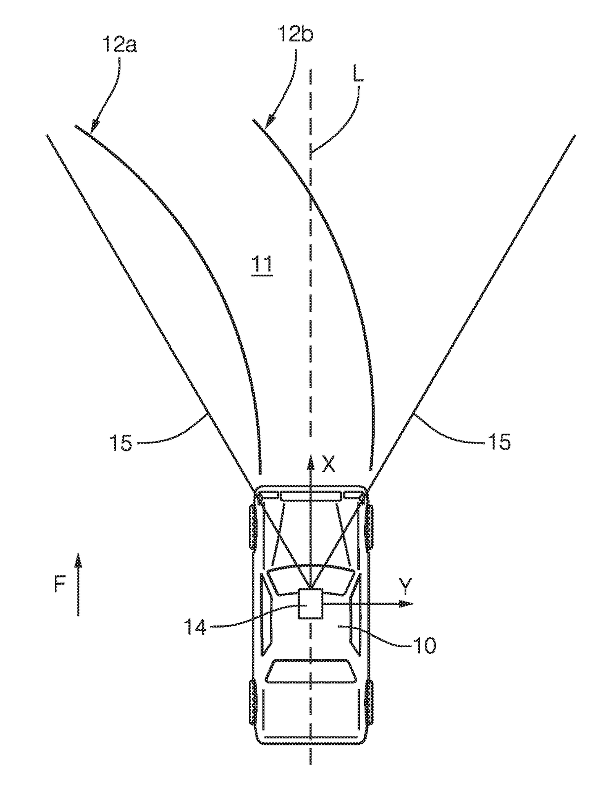
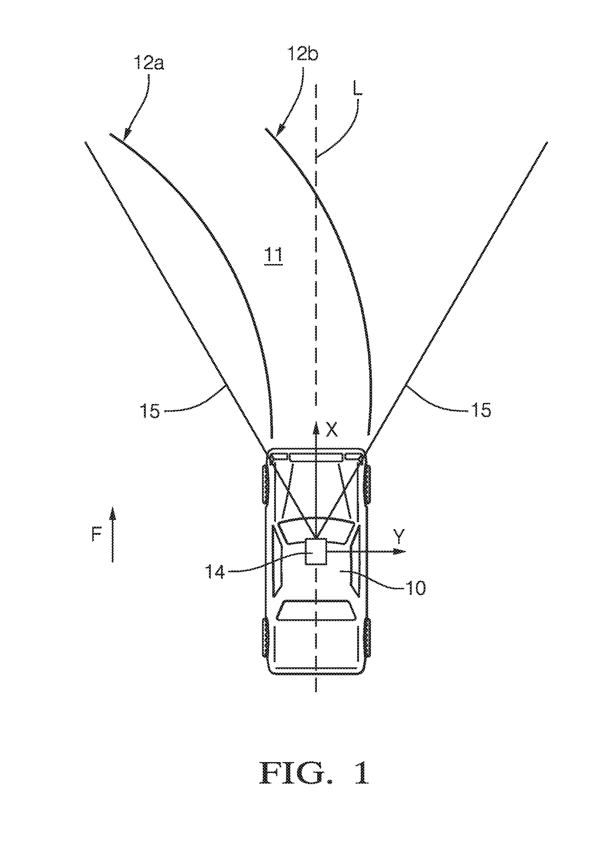
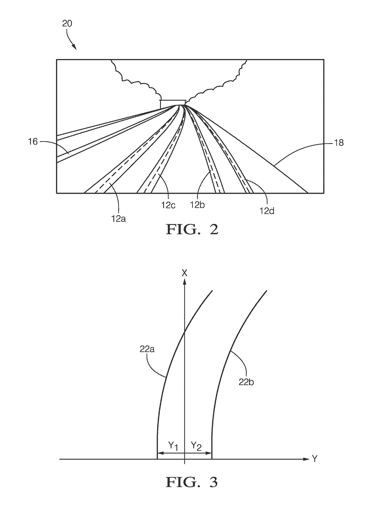
[0032]According to FIG. 1, a motor vehicle 10 is traveling on an own-lane 11 of a road in a driving direction F. The own-lane 11 is limited by a left lane marking 12a and a right lane marking 12b—by way of example, each in the form of a solid line. In a front area of the vehicle headliner, a camera 14 is mounted which continuously captures an image of the traffic space ahead of the motor vehicle 10, as shown by the lines of sight 15. The camera position spans the world coordinate system x, y. Furthermore, the camera 14 is coupled to a downstream image processing computer which is not shown in FIG. 1. An example of an image 20 of the traffic space ahead of the motor vehicle 10 captured by the camera 14 is shown in simplified form in FIG. 2.

[0033]The camera 14 and the associated image processing computer are part of a driver assistance system, for example, a system for supporting lane holding (lane departure warning system, LDW). Said system detects and tracks lane markings based on t...


PUM


Abstract

A method for lane detection for a camera-based driver assistance system includes the following steps: image regions in images that are recorded by a camera are identified as detected lane markings if the image regions meet a specified detection criterion. At least two detected lane markings are subjected to a tracking process as lane markings to be tracked. By means of a recursive state estimator, separate progressions are estimated for at least two of the lane markings to be tracked. Furthermore, for each of a plurality of the detected lane markings, a particular offset value is determined, which indicates a transverse offset of the detected lane marking in relation to a reference axis. By means of an additional estimation method, the determined offset values are each associated with one of the separate progressions of the lane markings to be tracked.

Description

CROSS-REFERENCE TO RELATED APPLICATION[0001]This application claims the benefit under 35 U.S.C. § 371 of published PCT Patent Application Number PCT / EP 2015 / 056717, filed Mar. 27, 2015 that claims priority to European Patent Application 14163567 filed Apr. 14, 2014, and published as WO2015 / 150256 on Oct. 8, 2015, the entire contents of which is hereby incorporated by reference herein.TECHNICAL FIELD OF INVENTION[0002]This disclosure generally relates to a method for lane detection for a camera-based driver assistance system having a camera attached to a vehicle for capturing images of a traffic space ahead of the vehicle, comprising the steps that in images captured by the camera that areas of the image are identified as recognized lane markings which meet a predetermined recognition criterion, and at least two recognized lane markings are subjected to a tracking process as lane markings to be tracked, wherein the temporal change of the course of the at least two lane markings to be...

Claims


Application Information

Patent Timeline
IPC IPC(8): G06K9/00H04N7/18G06T7/20
CPCG06K9/00798G06T7/277H04N7/181G06V20/588
Inventor MUETER, MIRKOZHAO, KUNSZUMILAS, LECH J.MUELLER, DENNISNUNN, CHRISTIAN
Owner APTIV TECH LTD
Why Eureka
Try Eureka