Optical wireless communication system

a wireless communication and optical technology, applied in the field of bilateral communication systems, can solve the problems of reducing the performance of the lan, increasing the volume, weight and required power of the system, and requiring a complicated mechanism and controlling system to achieve automatic servomechanism

Inactive Publication Date: 2007-03-06
STANLEY ELECTRIC CO LTD +1
View PDF14 Cites 10 Cited by
  • Summary
  • Abstract
  • Description
  • Claims
  • Application Information

AI Technical Summary

Benefits of technology

[0051]The present invention is carried out in view of the above-mentioned problems so as to provide an optical wireless communication system capable of preventing addresses in an address table from vanishing while the optical node is moving, even when both photo-detecting / emitting angles of optical repeaters and optical nodes are set wide, so that a relation between a mobile object and a network can be kept in the same manner as in the wired communication system. The present invention also provides the optical wireless communication capable of being operated normally, even when communication areas of a plurality of the optical repeaters are overlapped.

Problems solved by technology

And because a congestion of information in the system is aggravated when redundant information is received, so that a performance of the LAN is deteriorated.
When the computer is mounted on a mobile object such as a conveyor, a robot or the like, and is required to communicate while moving, the narrow directional angle of the optical node causes a problem.
When solution (1) is employed, very complicated mechanism and controlling system are required for attaining the automatic servomechanism.
As a result, volume, weight and required power are increased in the system, which will be controversial factors when this solution is employed in the mobile object.
Consequently, this solution would require a much higher cost.
Further if wider photo-detecting / emitting areas are attained by employing a plurality of optical repeaters, the more fatal following problem will be caused.
If signals from the optical repeaters AP1 and AP2 are simultaneously transmitted to the trunk network 3, there are probabilities that a data collision will occur and data will be destroyed.
In addition, there is also a problem that an upward transmittable area and a downward transmittable area do not coincide with each other.
In this case, if a protocol (for example TCP / IP) for administrating frame number is employed, a protocol stack in the computer PC2 is confused so that transmitting performance is remarkably deteriorated.
Even if a protocol not for administrating frame number is employed, transmitting performance is also deteriorated due to a redundant frame is transmitted in the network as illustrated in FIG. 10.
In other words, since the same frames are transmitted from the optical repeaters AP1 and AP2 to the trunk line, transmitting performance is deteriorated.
If the folded transmissions are transmitted, functions of the wired LAN will be deteriorated (a frame congestion will be caused).

Method used


Image

  • Optical wireless communication system
  • Optical wireless communication system
  • Optical wireless communication system

Examples


embodiment 1

[0068](Embodiment 1)

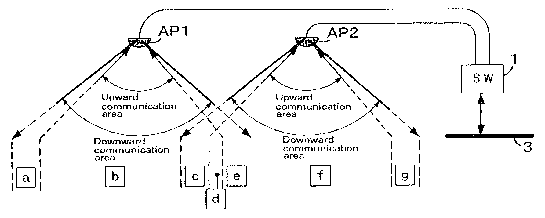
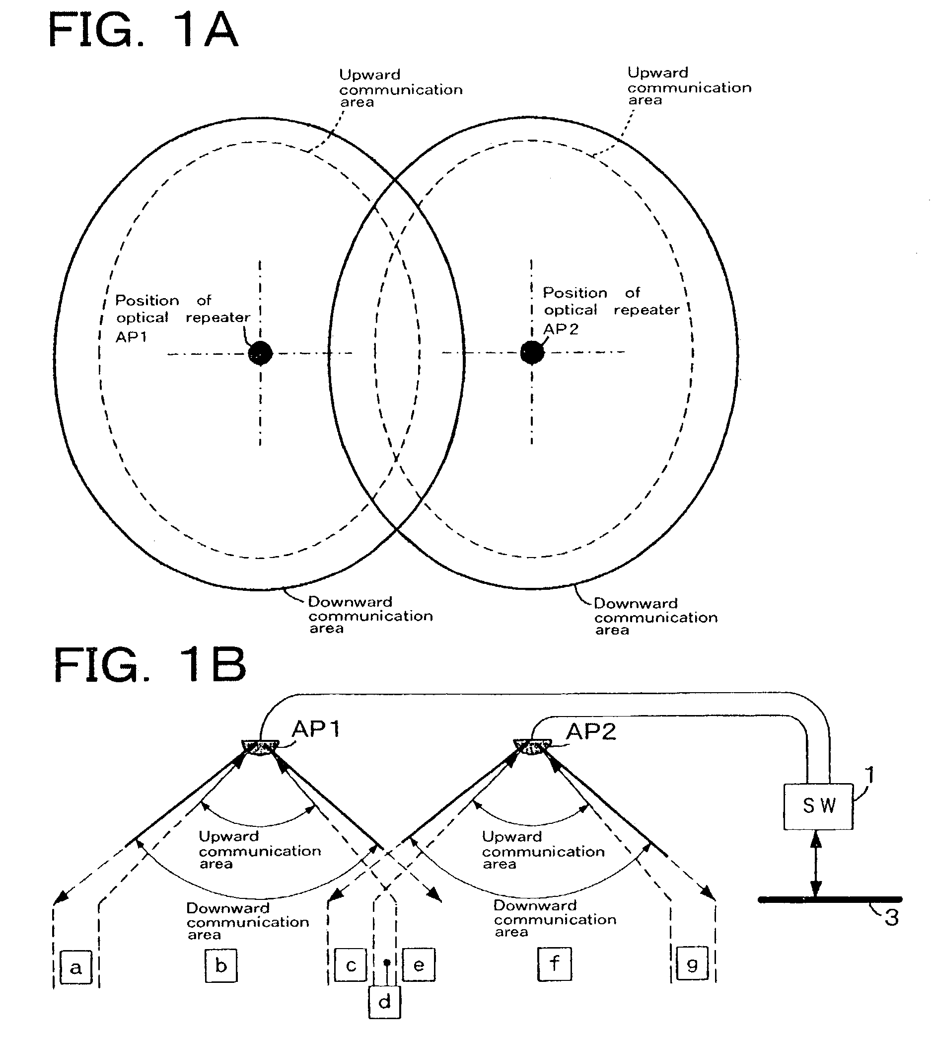
[0069]In the present embodiment, photo-detecting / emitting areas of the optical repeaters and the optical node are set wide directional angles. A plurality of the optical repeaters are arranged such that the photo-detecting / emitting areas of neighbor optical repeaters are overlapped each other, as satisfying the following conditions.

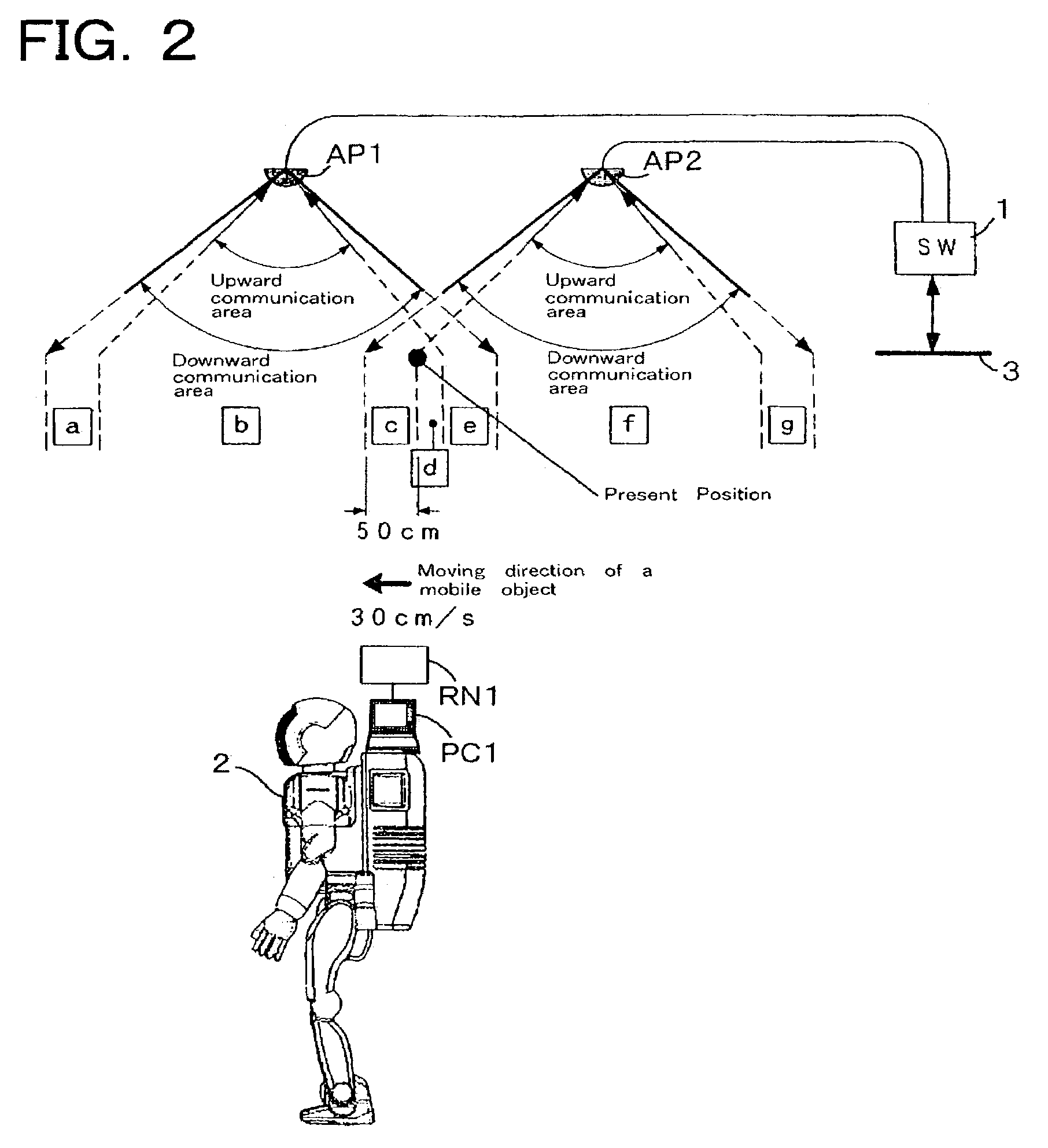
[0070]Addresses in an address table are prevented from vanishing, while the mobile object equipped with the optical node is moving so that the same functions as in a wired network are kept in the present wireless network.

[0071]Problems mentioned in “Brief Description of the Prior Art” occurring in overlapped areas are solved so that the wireless network performs normally even when photo-detecting / emitting areas of a plurality of optical repeaters are overlapped.

[0072]In order to attain the above-mentioned conditions, the present embodiment is constituted as follows.

[0073]A downward transmitting area is always set wider than an upward t...

embodiment 2

[0089](Embodiment 2)

[0090]The present embodiment is different in the following feature such that a filtering function is added to the transit post, from embodiment 1. Explanations on other functions of the present embodiment same as the embodiment 1 are omitted, and mainly different features of the present embodiment are explained.

[0091]In the present embodiment, photo-detecting / emitting areas of the optical repeaters and the optical node are set wide directional angles. A plurality of the optical repeaters are arranged such that the photo-detecting / emitting areas of neighbor optical repeaters are overlapped each other, as satisfying the following conditions.

[0092]Addresses in an address table are prevented from vanishing, while the a moving object equipped with optical node is moving so that the same functions as in a wired network are kept in the present wireless network.

[0093]Problems mentioned in “Brief Description of the Prior Art” occurring in overlapped areas are solved so th...


PUM


Abstract

The present invention provides a bilateral communication network system, particularly, a optical wireless communication system communicating information frames via an optical node mounted on a mobile object and a plurality of optical repeaters connected to a wired network, which can prevent transfer performance from deteriorating without increasing frames to be transferred. The optical wireless communication system is constituted as follows. A plurality of the optical repeaters having functions to switch information frames are attached to a ceiling. The optical node bilaterally communicating with the optical repeaters are mounted on a moving object such as a robot, a vehicle or the like. Information frames including address information of the optical node are periodically transmitted from an information processor connected to the optical node via optical wireless communication. The address information is continuously transmitted from the optical repeaters to a trunk network, and a filter function is arranged in the trunk network so as to make only one frame effective among frames with the same content.

Description

BACKGROUND OF THE INVENTION[0001]1. Field of the Invention[0002]The present invention relates to a bilateral communication system by a optical wireless communication, particularly relates to a optical wireless communication system where information frames are exchanged with an optical node mounted on a mobile object via a plurality of optical repeaters arranged in a wired network system.[0003]2. Brief Description of the Related Art[0004]Recently a wireless optical network (LAN) utilizing infrared rays was proposed and it has put to a practical use. FIG. 6 shows an outline of a system arrangement of such wireless optical networks utilizing infrared rays.[0005]In the system illustrated in FIG. 6, a plurality of optical repeaters AP functioning as access points, are arranged on a ceiling or walls of a building. These optical repeaters AP are connected to a trunk network (not shown in FIG. 6) via a transit post 1, sometimes called “a switching hub”, and optical repeaters AP optically an...

Claims


Application Information

Patent Timeline
Patent Type & Authority Patents(United States)
IPC IPC(8): H04B10/00H04B10/114H04L12/28H04L12/46H04L12/701
CPCH04B10/1149H04W88/04H04L45/00H04L12/4604
Inventor KAWABE, KOJIFURUKAWA, YOSHIKIYOKOYAMA, HIROKIOKA, HIROYUKIUCHIDA, DAISUKEHIROSAWA, KAZUNORIHIBIYA, KAZUYOSHI
Owner STANLEY ELECTRIC CO LTD
Why Eureka
Try Eureka