Inclination sensor

a technology of inclination sensor and inclination sensor, which is applied in the field of inclination sensor, can solve the problems of visual determination of inclination, severe affecting the trajectory of the ball, adding to the visual confusion, etc., and achieves significant accuracy, easy to understand and use.

Inactive Publication Date: 2007-03-13
EXELYS
View PDF32 Cites 17 Cited by
  • Summary
  • Abstract
  • Description
  • Claims
  • Application Information

AI Technical Summary

Benefits of technology

[0003]In accordance with embodiments of the present invention, an electronic device for the determination and display of surface inclination and the direction of such inclination is provided. The information regarding the inclination and direction of inclination can be displayed such that an end user can readily and easily comprehend and use the information without additional interpretation. Further, when the inclination is displayed in decimal values, a large range of inclination angles can be displayed with significant accuracy.

Problems solved by technology

In the sport of golfing, when a golfer attempts to hit the ball into the hole on a putting green, slight angles of green surface inclination may severely affect the ball's trajectory.
It can be difficult however, to visually determine the inclination of a golfing green at that spot which is close to the hole, particularly in situations where the green's entire topography is complicated by multiple, different inclinations distributed across its surface.
Further, the flagpole, traditionally placed in the center of the hole, is only rarely precisely vertical, adding to the visual confusion while assessing the green's inclination.

Method used


Image

  • Inclination sensor
  • Inclination sensor
  • Inclination sensor

Examples


Embodiment Construction

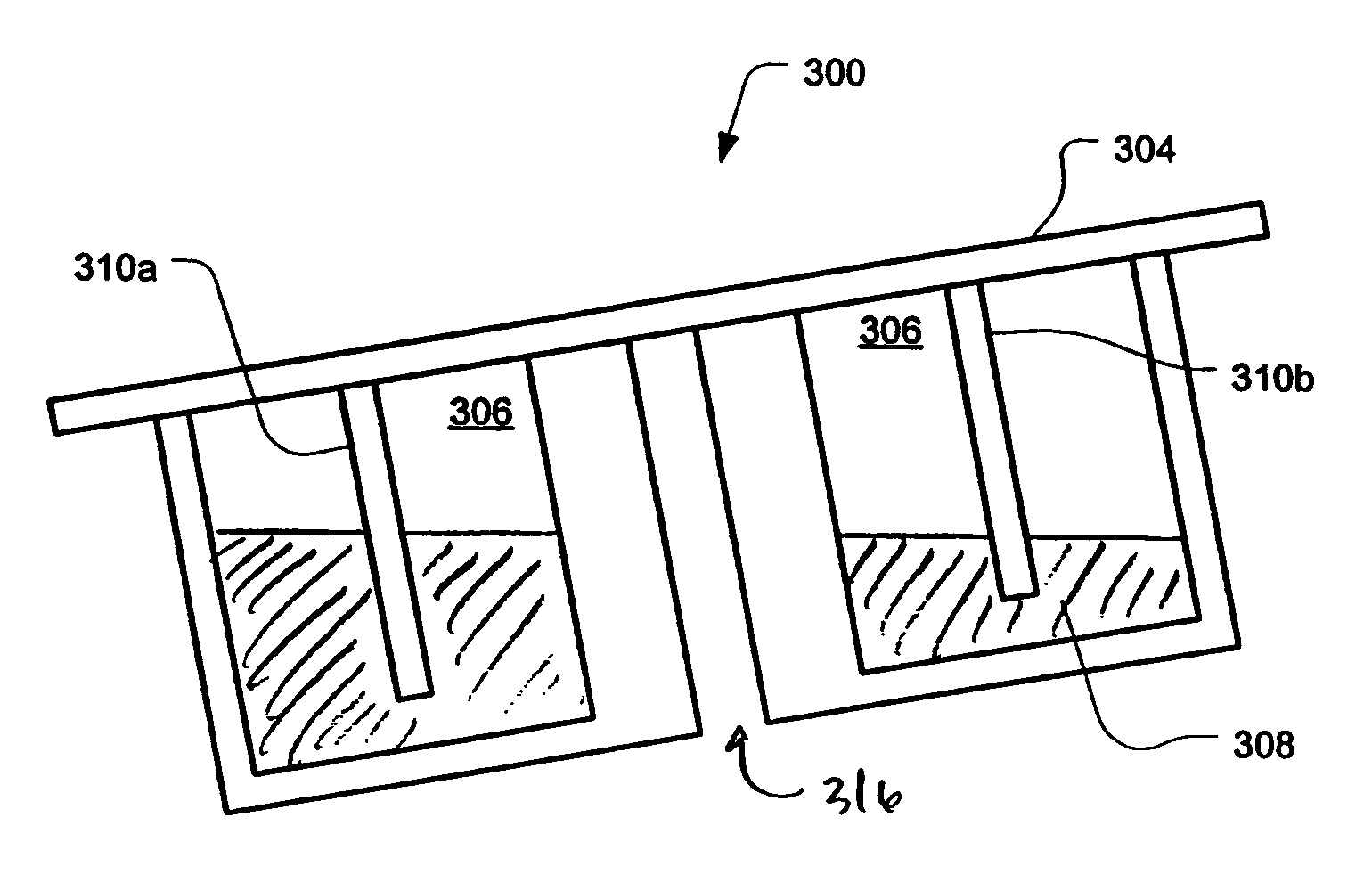
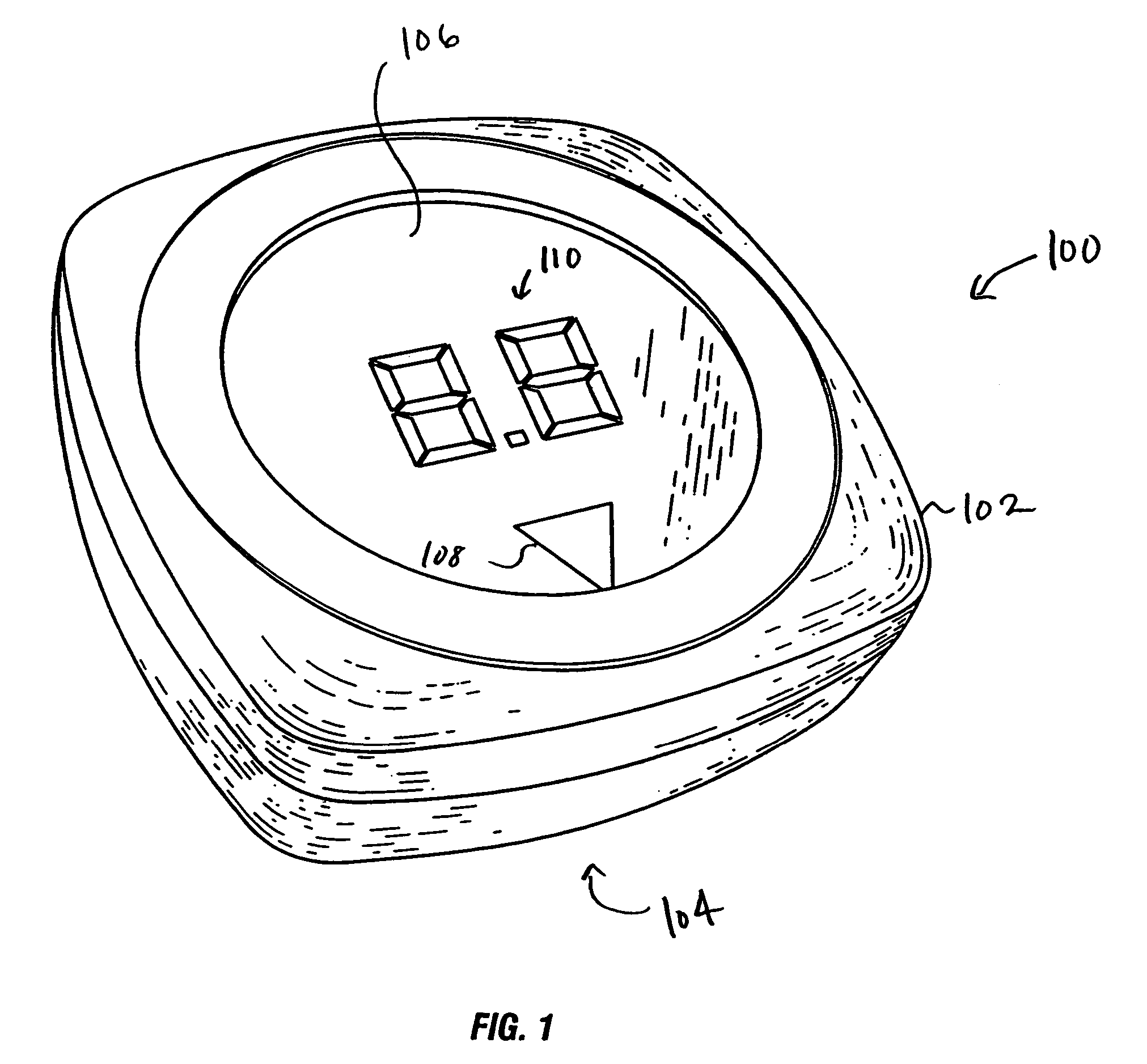
[0014]FIG. 1 is a perspective view of an inclination sensing device 100, in accordance with embodiments of the present invention. The inclination sensing device 100 may include a display 106 provided on the top surface of a small enclosure 102. The enclosure 102 includes a reference surface 104, shown in FIG. 1 as the bottom surface of the enclosure 102.

[0015]FIG. 5 is a flowchart of a method of measuring and displaying the angle and direction of inclination in accordance with embodiments of the present invention. In step 501, the inclination sensing device 100 is placed on the surface to be measured. This may be accomplished by positioning the reference surface 104 directly on the surface to be measured, such as the surface of the green immediately adjacent the golfer's ball. Next, in step 502, an electrical characteristic of the inclination sensor, such as capacitance, is measured. In step 503, the measured electrical characteristics are processed to determine the angle and direct...


PUM


Abstract

An electronic inclination sensor is provided for the determination and display of surface inclination and the direction of such inclination. The information regarding the inclination and direction of inclination can be displayed such that an end user can readily and easily comprehend and use the information without additional interpretation. Further, when the inclination is displayed in decimal values, a large range of inclination angles can be displayed with significant accuracy.

Description

CROSS-REFERENCE TO RELATED APPLICATIONS[0001]This application claims the benefit of U.S. Provisional Application No. 60 / 463,267, filed Apr. 15, 2003, the disclosure of which is incorporated herein in its entirety as if fully set forth below.BACKGROUND OF THE INVENTION[0002]In the sport of golfing, when a golfer attempts to hit the ball into the hole on a putting green, slight angles of green surface inclination may severely affect the ball's trajectory. This is particularly true in those areas of the putting green that are close to the hole and in the path of the ball. Knowledge of the inclination of the green in this critical area prior to putting can be advantageous to the golfer, so that he may compensate for such inclination while hitting the ball. It can be difficult however, to visually determine the inclination of a golfing green at that spot which is close to the hole, particularly in situations where the green's entire topography is complicated by multiple, different inclin...

Claims


Application Information

Patent Timeline
Patent Type & Authority Patents(United States)
IPC IPC(8): G01C9/06A63B57/00A63B71/06G01C9/18G01C9/20
CPCA63B57/00A63B71/0622G01C9/06G01C9/20A63B2071/0691A63B2220/18G01C2009/185G01C2009/062A63B2243/0029A63B2102/32
Inventor BARR, KEITH E.
Owner EXELYS
Why Eureka
Try Eureka