Visual fuel system for an engine welder

a fuel system and engine technology, applied in the direction of liquid handling, manufacturing tools, packaging goods types, etc., can solve the problems of prior engine welders, little, if any, warning to operators, and operator requirements, so as to minimize the damage to the fueling assembly components, minimize the impact of fluids on the interior, and facilitate service and installation

Active Publication Date: 2007-03-13
LINCOLN GLOBAL INC
View PDF58 Cites 13 Cited by
  • Summary
  • Abstract
  • Description
  • Claims
  • Application Information

AI Technical Summary

Benefits of technology

[0018]Another and / or alternative object of the present invention is to provide a fueling assembly which is easy to service and install.
[0019]Yet another and / or alternative object of the present invention is to provide a fueling assembly which has proper sealing, and which minimizes or prevents fluids from contaminating the interior of the engine driven device.
[0020]Still another and / or alternative object of the present invention is to provide a fueling assembly which minimizes damage to the fueling assembly components during the operation of the engine driven device.
[0025]Yet another and / or alternative object of the present invention is to provide a fuel assembly that enables an operator to fill a fuel tank and simultaneously monitor the fuel gauge.
[0030]Still yet a further and / or alternative object of the present invention is to provide a grommet having a sloped surface which facilitates in the flow of flows out of the grommet.

Problems solved by technology

This position of the gas tank opening of the welder had several disadvantages, one which was that an operator was required to bend down to the ground to open, fill and then reseal the gas tank.
Another disadvantage of prior engine welder fuel assemblies was that the close proximity of the gas tank opening to the top of the gas tank provided little, if any, warning to the operator during fueling that the gas tank was approaching a full condition.
Prior engine welders had the further disadvantage of allowing fuel that spilled on the welder during fueling to flow all over the top and / or side surface of the engine welder housing.
Such fuel spillage could result in the defacing of the engine welder housing and / or damage to the internal components of the engine welder.
Although the fuel assembly design of the RANGER 8 and 9 has been commercially successful, monitoring of the fuel level in the fuel tank during operation of the engine welder and during the filling of the fuel tank remained as issues for the engine welder.

Method used


Image

  • Visual fuel system for an engine welder
  • Visual fuel system for an engine welder
  • Visual fuel system for an engine welder

Examples


Embodiment Construction

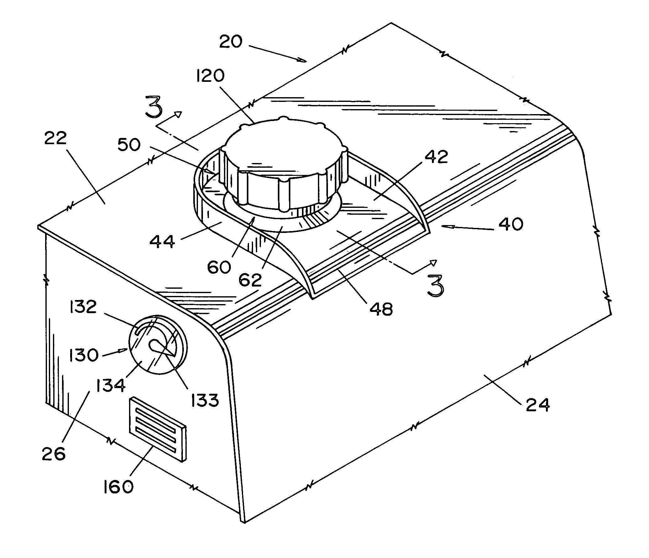
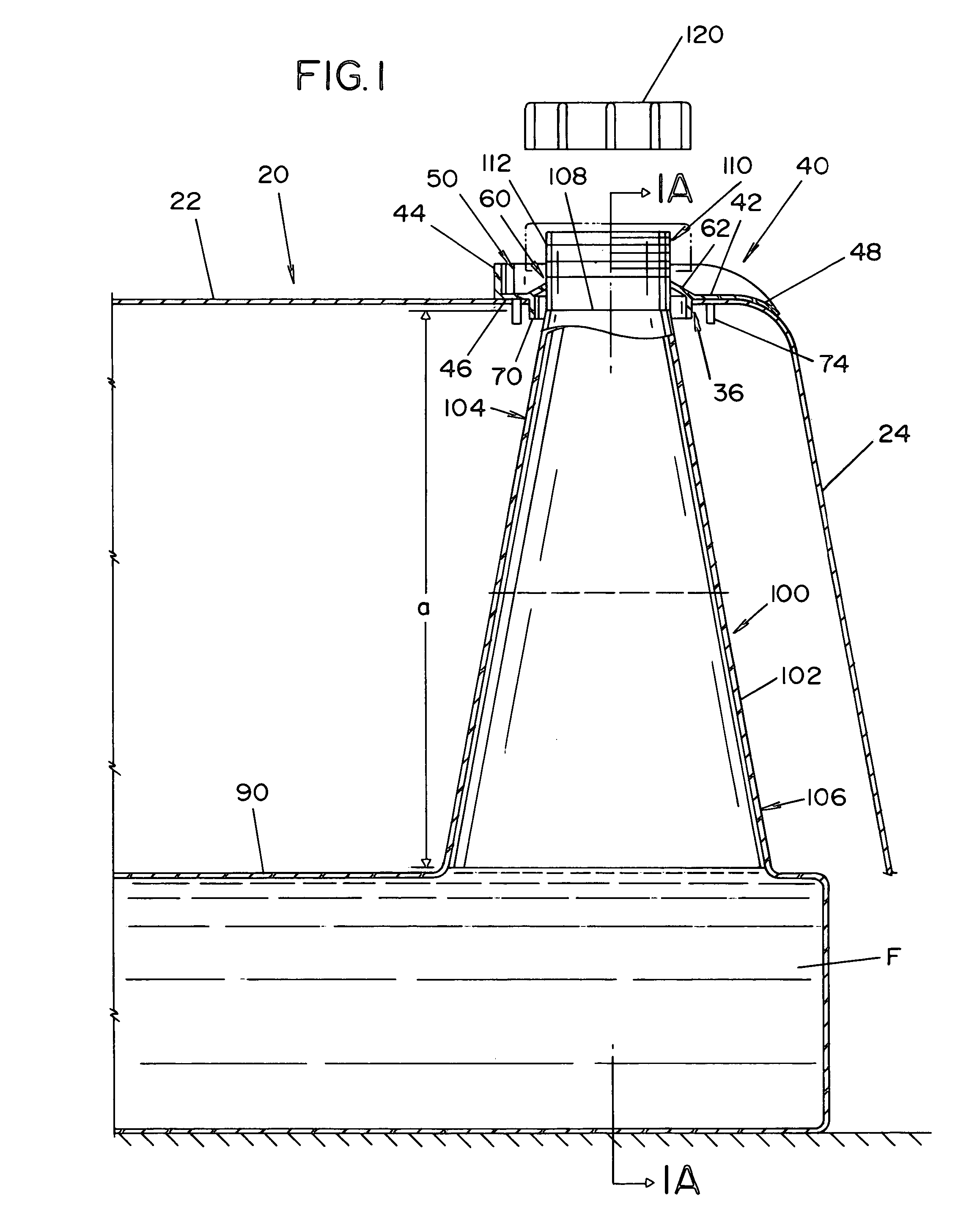
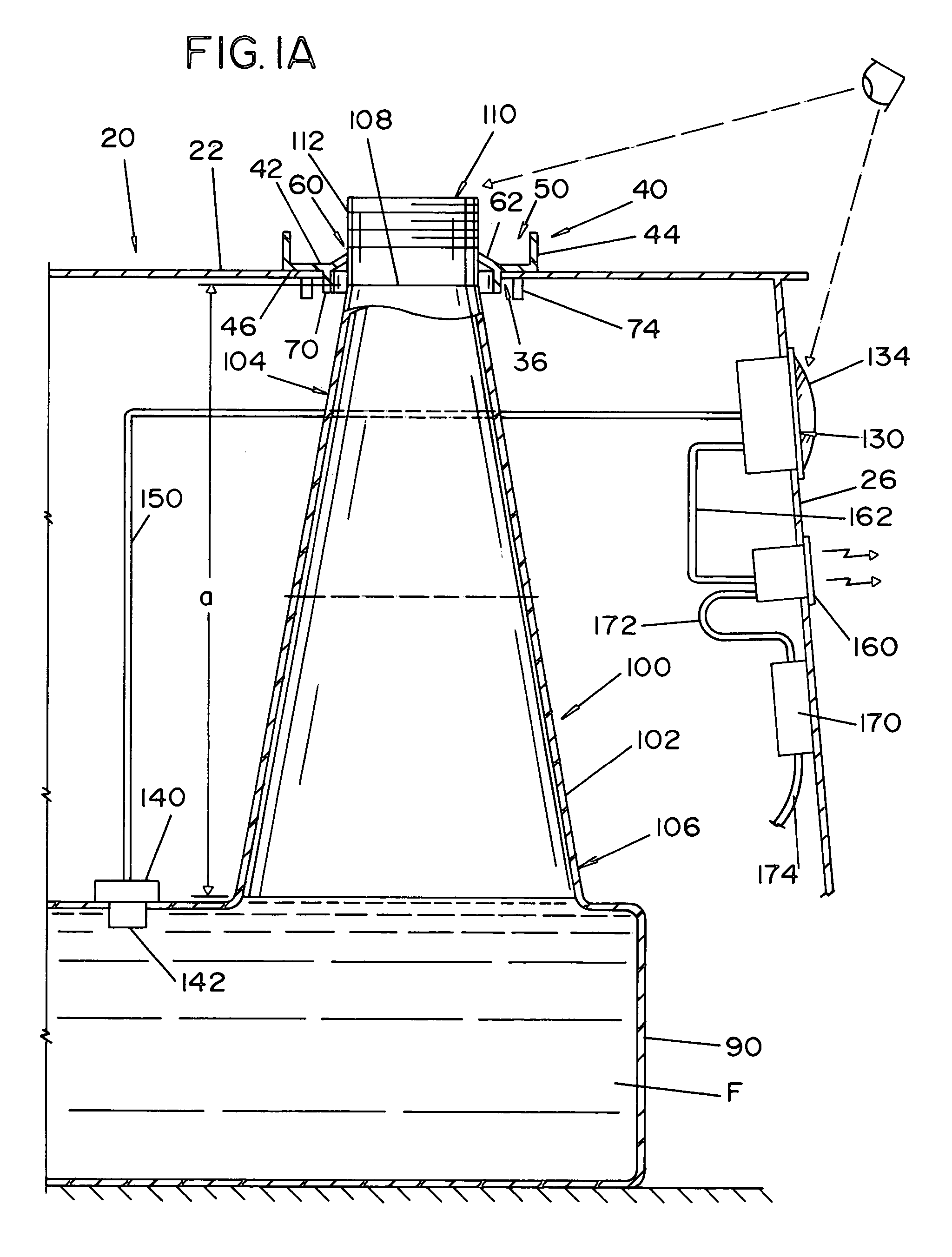
[0053]Referring now to the drawings, wherein the showings are for the purposes of illustrating the preferred embodiments of the invention only and not for the purpose of limiting the same, FIG. 1 illustrates a portion of a cross-section of housing 20 which is secured to a typical engine welder or other engine driven device, not shown. Housing 20 includes a top region 22 and two side regions 24 and 26. The housing is designed to encase at least a portion of the internal components of the engine welder or other engine driven device. Typically positioned in top region 22 of the housing is an exhaust pipe opening, not shown, and a motor access opening, not shown. The housing is typically secured by bolts, screws or other means to the frame of the engine welder or other engine driven device. The configuration of the exhaust pipe opening and motor access opening are well known in the art and are disclosed in U.S. Pat. Nos. 5,928,535; 6,172,332; 6,263,926; and 6,296,027, which are incorpor...


PUM


Abstract

A fueling assembly for a fuel tank positioned in an engine driven welder. The fueling assembly includes a filler tube, a fuel level monitor and a grommet. The filler tube has a bottom portion and a top portion. The bottom portion of the filler tube has a cross-sectional area that is greater that any region in the top portion of the filler tube. The fuel level monitor includes a fuel level sensor position in the fuel tank and / or filler tube. The fuel level monitor includes a fuel level indicator positioned on a side of the housing so as to enable an operator to simultaneously view the fuel level indicator and the opening used to direct fuel into the filler tube during the filling of the fuel tank. The grommet at least partially seals the tube access opening to inhibit fluids entering the interior of the housing of the engine driven welder.

Description

BACKGROUND OF THE INVENTION[0001]This invention pertains to engine driven welding machines, and more particularly to arrangements for filling the fuel tanks of welding machine engines.INCORPORATION BY REFERENCE[0002]U.S. Pat. Nos. 5,928,535; 6,172,332; 6,263,926; 6,296,027 and 6,472,635; U.S. patent application Ser. No. 10 / 099,677 filed Mar. 14, 2002; and the Operator's Manual for the RANGER 9 are incorporated herein by reference and illustrate various types of grommets that can be used fuel assembly arrangements for engine welders.BACKGROUND OF THE INVENTION[0003]Engine driven welding machines include a gas powered engine to run a generator which supplies power to the welding electrode. Consequently, the fuel tank for the gas powered engine must be periodically refilled with fuel. Years ago, the gas tank opening for the engine welder was located at or near the base of the engine welding machine. This position of the gas tank opening of the welder had several disadvantages, one whic...

Claims


Application Information

Patent Timeline
Patent Type & Authority Patents(United States)
IPC IPC(8): B65B1/04B23K9/32
CPCB23K9/32
Inventor BENDER, DAVID J.STAPP, JASON R.
Owner LINCOLN GLOBAL INC
Why Eureka
Try Eureka