Bottom bracket for bicycles

a technology for bicycles and bottom brackets, which is applied in the direction of bicycles, rigid support of bearing units, transportation and packaging, etc., can solve the problems of disadvantage of bicycle riders and excessive friction of crankshafts, and achieve low resistance pedaling, increased versatility, and prevent crankshaft fretting/chattering

Inactive Publication Date: 2016-07-12
WOFENBARGER WESLEY WARREN
View PDF19 Cites 11 Cited by
  • Summary
  • Abstract
  • Description
  • Claims
  • Application Information

AI Technical Summary

Benefits of technology

[0030]Another object is to provide a lightweight bottom bracket bearing assembly that provides increased versatility with respect to the crank shaft assembly without compromising the strength of the bottom bracket bearing assembly.
[0031]A further object of our invention is to provide improved fitments for bearings installed in bicycle bearing module bores.
[0032]Another object is to prevent fretting / chattering of the crankshaft.
[0033]Another object is to enable smooth, low resistance pedaling.
[0034]Another object is to provide a bottom bracket bearing assembly that maintains alignment of the bearings' integral, constituent parts, such as inner and outer races and individual ball bearing, and reduces radial compression, or preload of said parts.
[0035]An object of the present invention is to provide a bicycle bottom bracket assembly that is relatively easy to service and / or replace due to its modular design.

Problems solved by technology

Forces experienced by the crankshaft bearings might otherwise dislodge, disorient, or deform bearings, resulting in excessive friction on the crankshaft, which disadvantages the bicycle rider.

Method used


Image

  • Bottom bracket for bicycles
  • Bottom bracket for bicycles
  • Bottom bracket for bicycles

Examples


Embodiment Construction

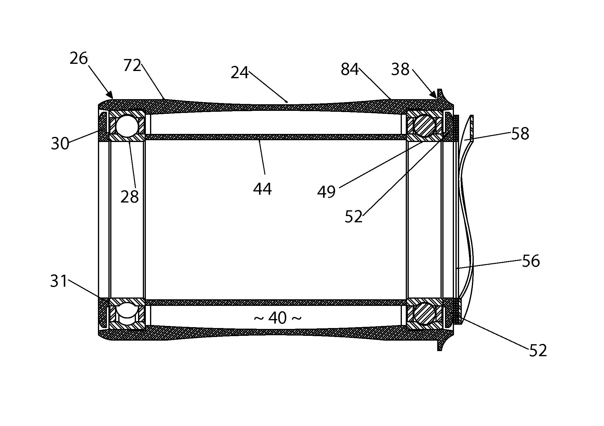
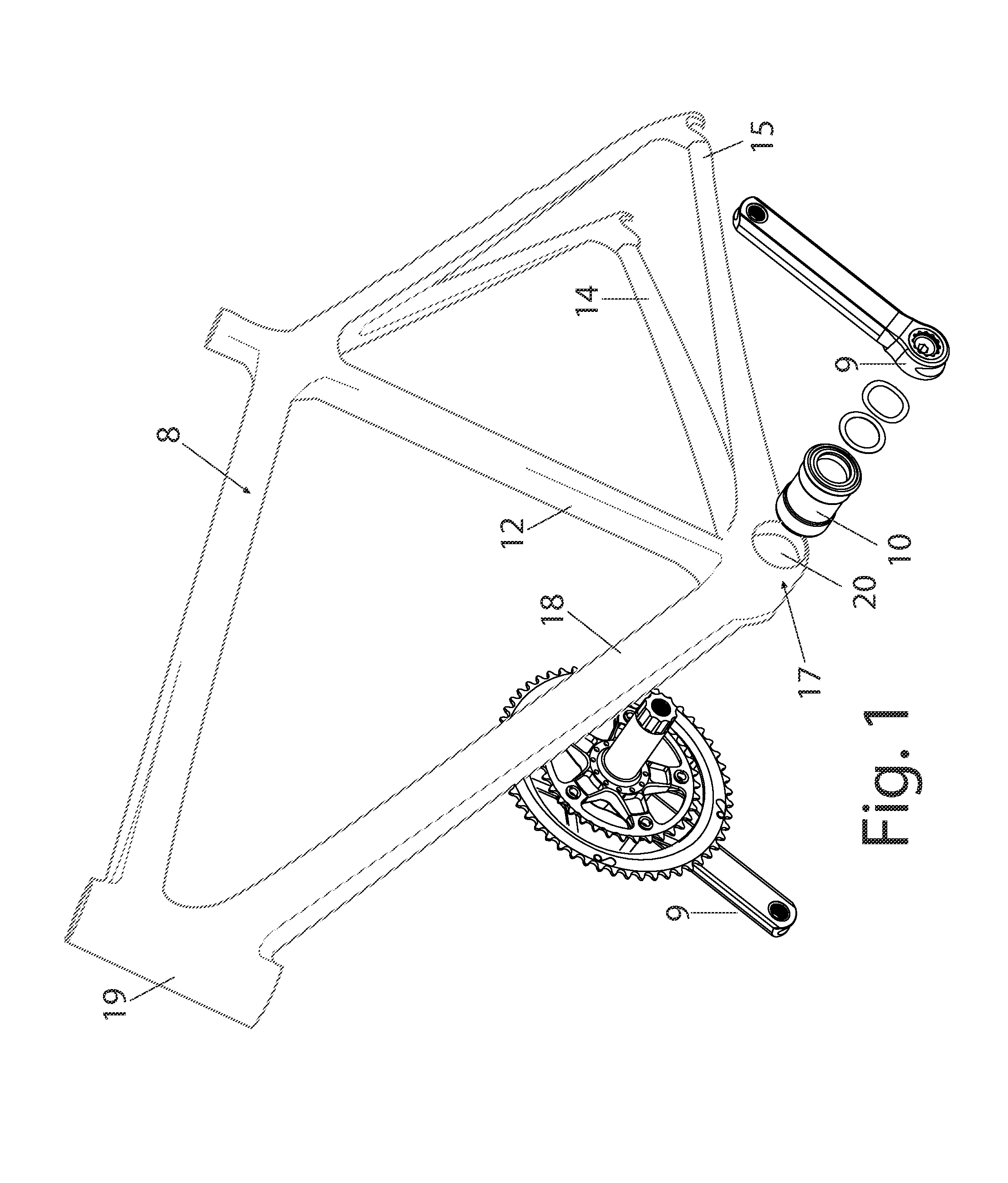
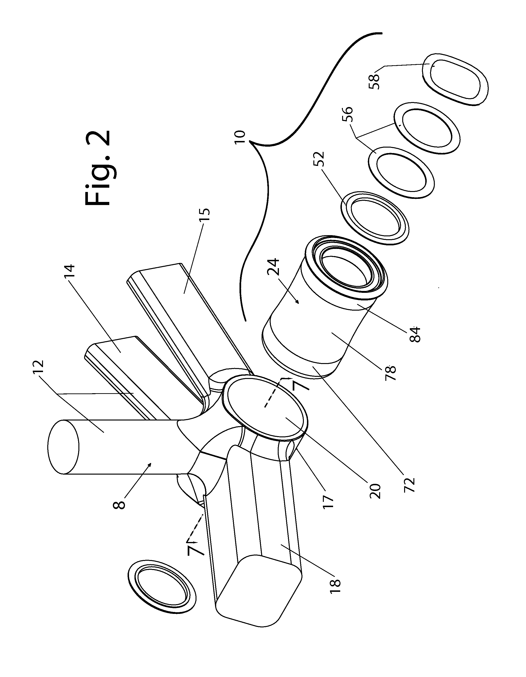
[0054]Turning now to FIGS. 1 and 2, our modular bottom bracket bearing assembly 10 and a conventional, typical crank set 9 are disposed proximate a typical, unthreaded, press fit, or friction fit composite bicycle frame that is generally indicated by the reference numeral 8. FIG. 2 shows our modular bottom bracket assembly disposed proximate the lower section 9 of the typical, unthreaded, press fit or friction fit composite bicycle frame 8. Composite bicycle frame 8 comprises a frame reinforcement element 12 and a pair of diverging, tubular frame elements 14 and 15 that rearwardly project from the frame bottom bracket shell 17. As will be recognized by those skilled in the art, the bicycle rear wheel and suitable drive sprockets will be disposed between the ends of the elements 14, 15. A generally tubular, forwardly projecting frame downtube 18, extends from frame bottom bracket shell 17 at an angle with respect to the tubular frame elements 14 and 15, and supports steering tube 19 ...


PUM


Abstract

A bottom bracket assembly for bicycle frames aligns crankshaft bearings. The assembly is press fitted into the bottom bracket shell to journal the crankshaft. An elongated, rigid, unibody sleeve comprises a terminal end and a spaced apart leading end which both receive and support a radial contact bearing that is press fitted into a machined bore. Each bore comprises an interference fit zone for bearing retention and a larger, pressure relief zone comprising a channel and an adjacent, buffering slope that compensates for stresses. Dust shields coaxially abut the bearing exteriors. An inner, tubular buttress bushing coaxially occupies the sleeve interior and extends between the spaced apart bearings to brace them. Externally the sleeve has a pair of integral, friction retention contact interfaces separated by a reduced diameter optimization zone. The sleeve terminal end has an integral stop flange that abuts the frame bottom bracket shell contacting the crank arm.

Description

CROSS REFERENCE TO RELATED APPLICATION[0001]This utility patent application is based upon, and claims priority from, U.S. Provisional patent application Ser. No. 61 / 911,836, filed Dec. 4, 2013, entitled “Bottom Bracket for Bicycles”, by inventors Wesley Warren Wolfenbarger and Gary Edward Mailhiot Jr., the entire disclosure of which is hereby incorporated by reference.BACKGROUND OF THE INVENTIONI. Field of the Invention[0002]The present invention relates generally to improvements in bicycle bearing bottom brackets in which a rotatable crankshaft is journaled for rotation. More particularly, the present invention relates to single-piece, bearing modules that support bearings disposed at opposite ends of the crankshaft proximate the bicycle pedals, and to bearing fitments for said bearings.[0003]Bicycling has grown in popularity for numerous reasons. Bicycling is a popular form of recreation, offering the rider vigorous outdoor exercise. Of course, bicycling is a means of transportati...

Claims


Application Information

Patent Timeline
Patent Type & Authority Patents(United States)
IPC IPC(8): F16C13/02F16C9/02F16C35/077F16C43/04
CPCF16C9/02F16C35/077F16C2326/28B62M3/003F16C19/546
Inventor WOLFENBARGER, WESLEY WARRENMAILHIOT, JR., GARY EDWARD
Owner WOFENBARGER WESLEY WARREN
Why Eureka
Try Eureka