Emergency evacuation system for high-rise buildings

a high-rise building and evacuation system technology, applied in the direction of building rescue, life-saving devices, etc., can solve the problems of complicated and expensive electronic control systems, limited usefulness in high-rise buildings, and suffer from several drawbacks and disadvantages, so as to achieve safe and quick evacuation

Inactive Publication Date: 2007-03-13
FUHRMANN KURT F
View PDF21 Cites 9 Cited by
  • Summary
  • Abstract
  • Description
  • Claims
  • Application Information

AI Technical Summary

Benefits of technology

[0011]The general aim of the present invention is to provide a new and

Problems solved by technology

These prior systems take many forms, and range from simple fabric chutes to complicated and expensive, electronically controlled systems.
Such arrangements suffer from several drawbacks and disadvantages in relation to use in a high-rise building.
They have limited usefulness in a high-rise building because of the height of the building, and therefore the drop through which a person muse descend.
They are not suitable for use on the inside a building because, among other things, the fabric escape chute would be relatively easily damaged, and special provisions such as in Putman would be required to protect the user from the dangers of a fire proximate the chute.
They also can not be easily used by an injured or

Method used


Image

  • Emergency evacuation system for high-rise buildings
  • Emergency evacuation system for high-rise buildings
  • Emergency evacuation system for high-rise buildings

Examples


Embodiment Construction

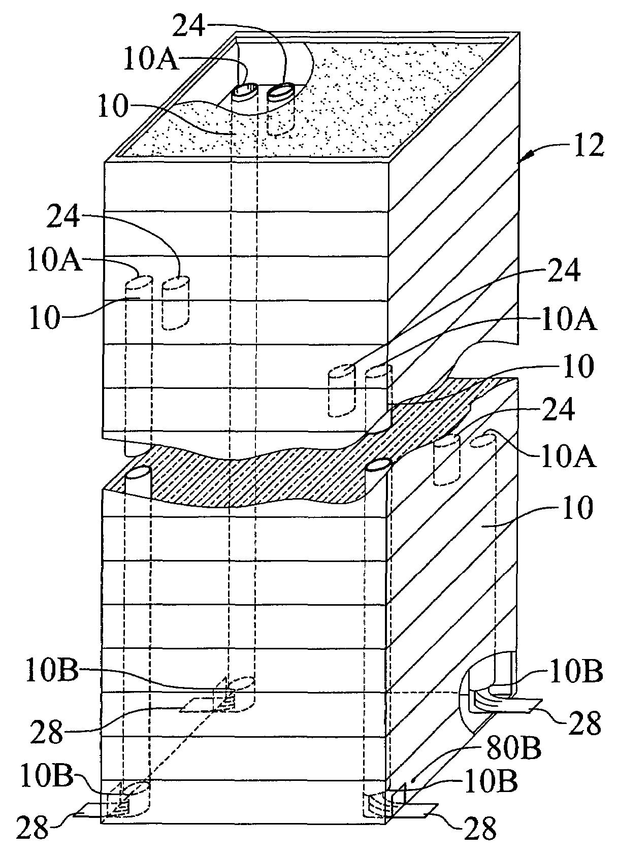
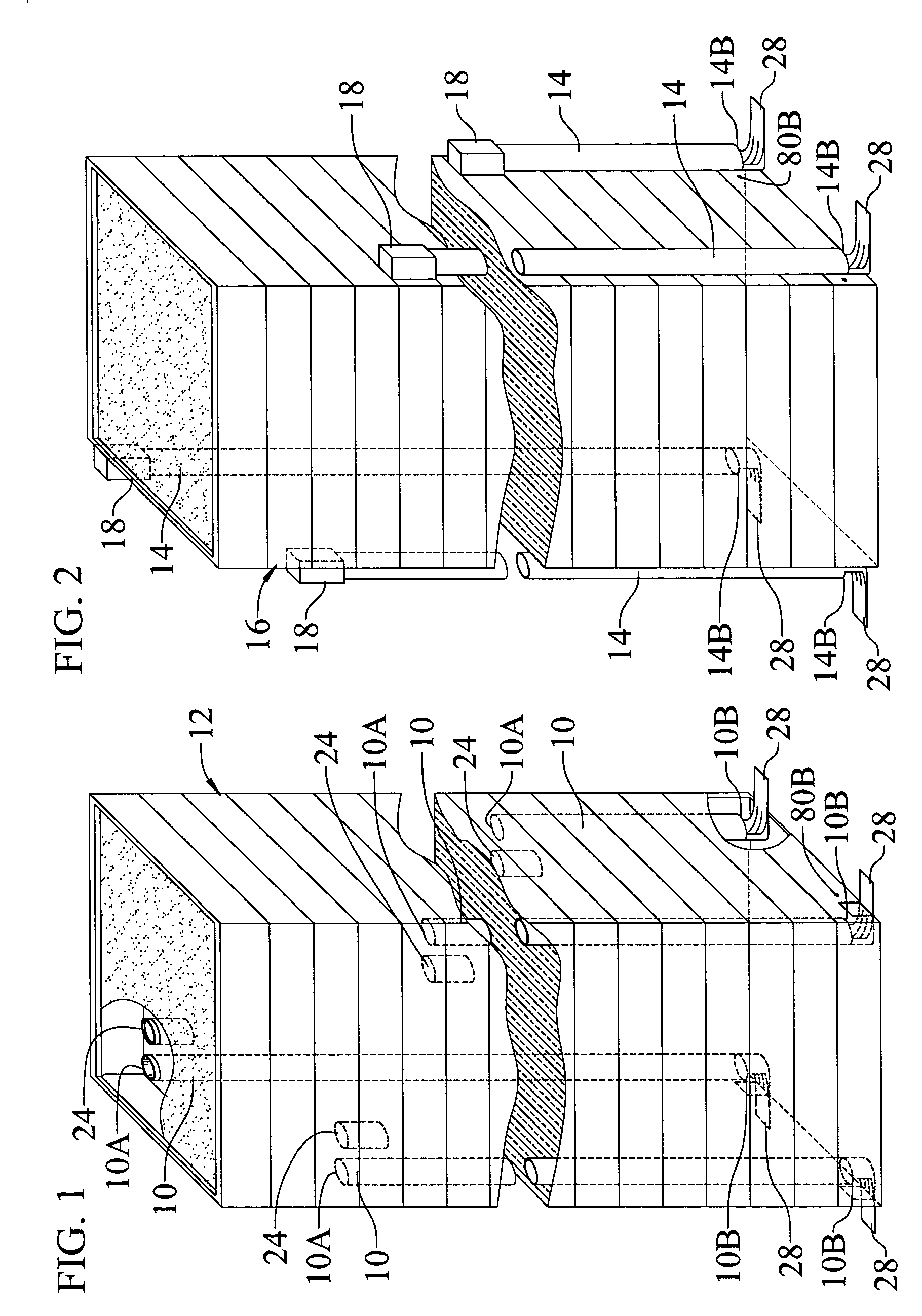
[0039]The present invention relates to an evacuation system comprising one or more evacuation stations for a high-rise building. An evacuation system in accordance with the invention shown in FIG. 1 includes four evacuation stations 10 as installed internal in a high-rise building 12. Alternately, or in addition, an evacuation system in accordance with the invention may include evacuation stations 14 installed onto the outside of a building such as an existing building 16 shown in FIG. 2. Except as modified with an external housing structure 18 to provide protection of the entrance to the evacuation station from the outside environment, the components, description and operation of the internal evacuation station 10 and the external evacuation station 14 are substantially the same.

[0040]The evacuation stations 10, 14 are provided with entry locations 10A, 14A at designated upper floors of the building, and building exit locations 10B, 14B established at ground level. Evacuation stati...


PUM


Abstract

An evacuation system for high-rise buildings includes an evacuation tube that extends vertically from an entrance on an upper floor to ground level, and a carrier that descends freely through the tube to swiftly carry a person from the upper floor to the ground. A storage tube holds multiple carriers near the entrance to the evacuation tube. The evacuation tube is configured to control the rate of descent of the carrier via established radial clearances and resulting progressively increasing pneumatic pressured-air damping under the carrier, to achieve an initial rapid descent, then a slower descent as the carrier approaches ground lever. Exiting the evacuation tube in the carrier is controlled through large sequenced valves that establish an airlock between the inside of the tube and the outside environment.

Description

BACKGROUND OF THE INVENTION[0001]1. Field of Invention[0002]The present invention relates generally to an evacuation system for high-rise buildings.[0003]More particularly, the invention relates to an evacuation system suitable for installation both on the outside of a high-rise building, and internal in the building, which does not rely on electric power for operation, and which is capable of safe, swift evacuation of all persons from upper floors in the building.[0004]2. Description of Prior Art[0005]The art is replete with evacuation systems for multi-story and high-rise buildings. These prior systems take many forms, and range from simple fabric chutes to complicated and expensive, electronically controlled systems.[0006]Fire escapes made from fabric or mesh chutes are disclosed in, for example, Putman U.S. Pat. No. 342,810, Bartley U.S. Pat. No. 1,265,165, Barker U.S. Pat. No. 4,398,621 and Orii et al. U.S. Pat. No. 4,162,717. Such arrangements suffer from several drawbacks and...

Claims


Application Information

Patent Timeline
IPC IPC(8): A62B1/20
CPCA62B1/20
Inventor FUHRMANN, KURT F.
Owner FUHRMANN KURT F
Why Eureka
Try Eureka