Switched-capacitor power supply system and method

a power supply system and capacitor technology, applied in the field of power supplies, can solve the problems of limiting the ability of contemporary microprocessors to meet the increasing demands of contemporary microprocessors, slow synchronous response, and limiting switching rates

Inactive Publication Date: 2007-03-13
INTEGRAL WAVE TECH
View PDF53 Cites 134 Cited by
  • Summary
  • Abstract
  • Description
  • Claims
  • Application Information

AI Technical Summary

Problems solved by technology

Typical synchronous buck regulators have certain inherent constraints that limit their ability to satisfy the increasing demands of contemporary microprocessors.
Such designs exhibit large input capacitances that limit switching rates.
The slow response of synchronous buck topologies and other power supply schemes may introduce instabilities in the feedback loop.
This increases the demands on the voltage regulator to accommodate changes in load requirements.

Method used


Image

  • Switched-capacitor power supply system and method
  • Switched-capacitor power supply system and method
  • Switched-capacitor power supply system and method

Examples


Embodiment Construction

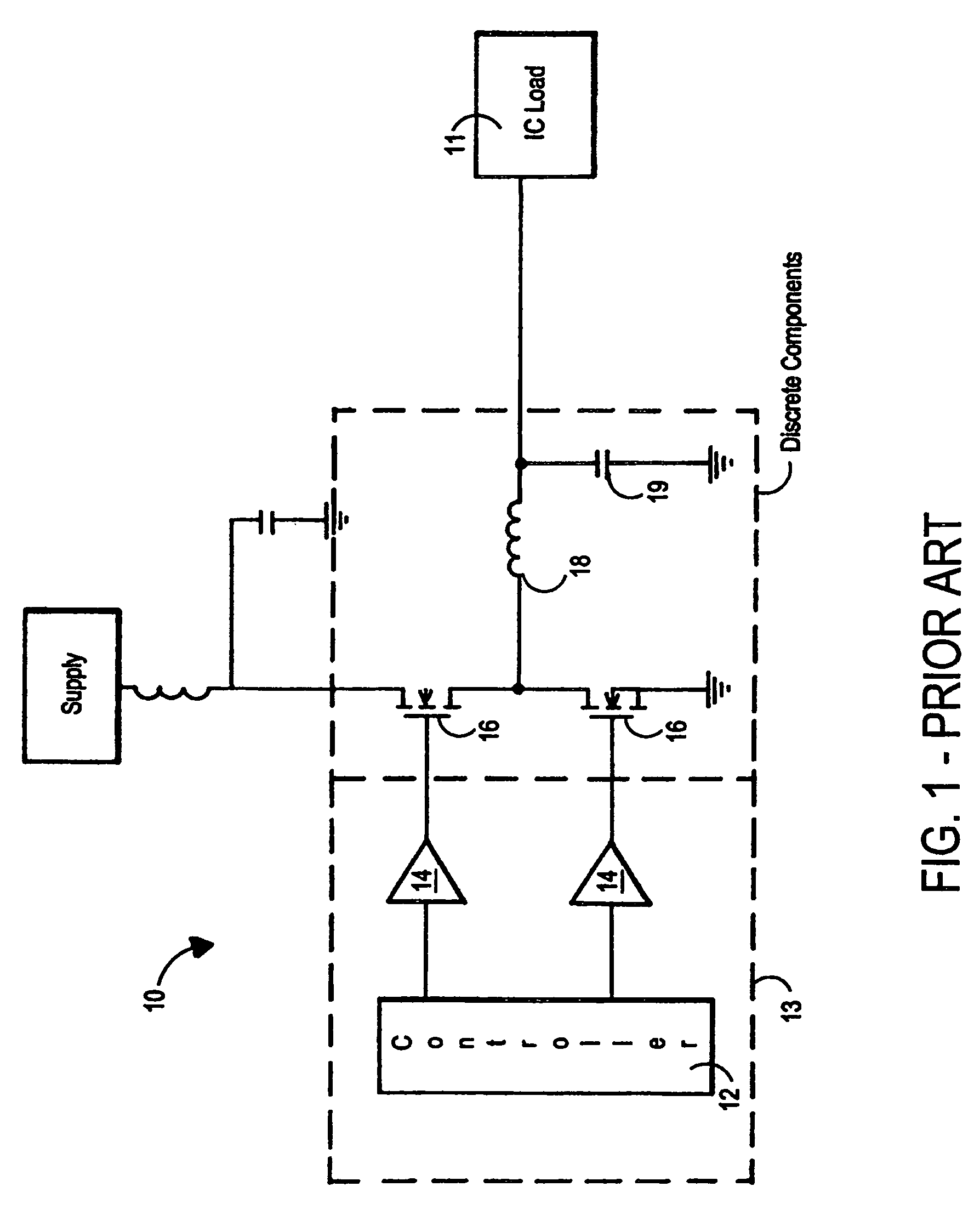
[0047]FIG. 1 depicts a prior art synchronous buck topology commonly used as a power supply for microprocessors and other demanding loads. Prior art system 10 includes a controller 12 for controlling a pair of drivers 14. Drivers 14 control power FETs 16, which deliver current to series inductor 18 and output capacitor 19. Controller 12 and drivers 14 may be discrete parts, or may be combined into an integrated chip 13, while FETs 16, series inductor 18, and output capacitor 19 are typically large, discrete, board-mounted components. Series inductor 18 and output capacitor 19 store energy for supply to load 11.

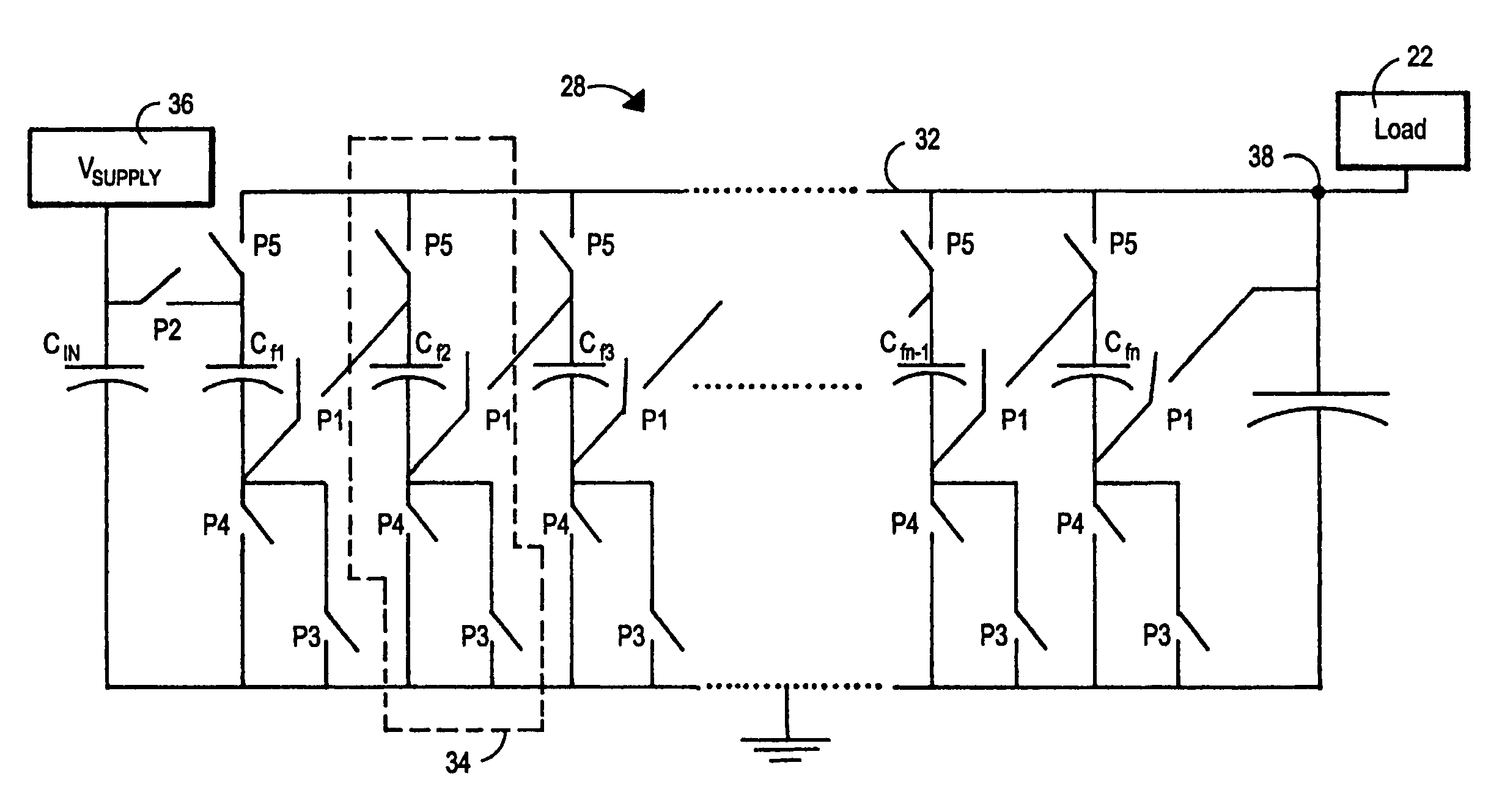
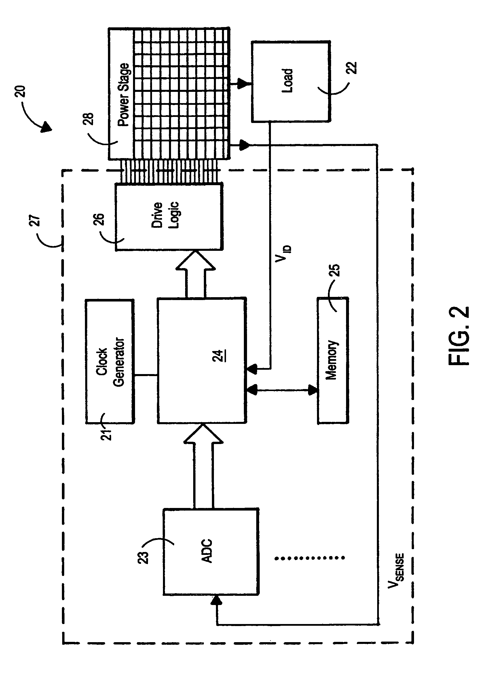
[0048]FIG. 2 provides a high-level block diagram of one embodiment of the present invention. FIG. 2 shows converter system 20 (or “converter 20”) which supplies load 22 with power. Converter system 20 has a control stage 27 and a power stage 28.

[0049]In this embodiment, load 22 provides voltage information through signal VID to control logic 24. Typically signal VID is carried ...


PUM


Abstract

A plurality of thin-film capacitors are grouped in phases. A control circuit switches each phase between charging and discharging states devised to supply one or more loads with controlled power.

Description

TECHNICAL FIELD[0001]The present invention relates to power supplies for integrated circuits, microprocessors, and other high-speed electronic systems.BACKGROUND OF THE INVENTION[0002]Modern electronic circuits such as, for example, ASICs, FPGAs, and microprocessors, have a broad range of current demands ranging from very high peak currents to relatively low quiescent currents. Although switching regulators can be designed to be highly efficient over a moderate range of load currents, future generations of electronic circuits will probably demand higher maximum output currents and greater dynamic range from power supplies. The modern trends toward increasing numbers of board-level voltage supplies, lower voltages, and smaller circuit board sizes with increased cooling concerns tends to create a growing need to use point-of-load (POL) voltage converters (or as they are called in some embodiments, “voltage regulators”). Further, such trends also tend to create the need to incorporate ...

Claims


Application Information

Patent Timeline
Patent Type & Authority Patents(United States)
IPC IPC(8): G05F3/02H01L27/108H02H7/16H02M3/07H02M3/335
CPCH02M3/07H02M2001/009H01L24/73H01L2224/16265H01L2224/32245H01L2224/48091H01L2224/48247H01L2224/73265H01L2924/14H01L2924/15311H01L2924/15321H01L2924/181H01L2924/19041H01L2924/19042H01L2924/19043H01L2924/19105H01L2924/19107H02M1/009H01L2924/00012H01L2924/00014H01L2924/00
Inventor AZRAI, FIRASYATES, MICHAELNELMS, DAVID
Owner INTEGRAL WAVE TECH
Why Eureka
Try Eureka