Surrounding surveillance apparatus and mobile body

a technology of surveillance apparatus and mobile body, which is applied in the field of surround-based surveillance system, can solve the problems of rear-end crash, narrow view of vehicle drivers and pedestrians, and increase in traffic accidents, so as to prevent collision or confirm safety more accurately, the effect of preventing collision or confirming safety

Active Publication Date: 2007-03-13
SHARP KK
View PDF17 Cites 36 Cited by
  • Summary
  • Abstract
  • Description
  • Claims
  • Application Information

AI Technical Summary

Benefits of technology

[0034]The omnidirectional vision sensor is provided at, for example, a lower position of at least one of left-and right-hand outside rearview mirrors (door mirrors) of a mobile body (e.g., a vehicle, etc.), which is a blind spot from the driver (user) with the omnidirectional vision sensor is horizontally oriented (the optical axis is horizontally oriented). Therefore, an overhead view image ranging from a front view to a rear view near a side of the vehicle, which is easy for the vehicle driver to understand, is obtained. Also, front and rear visual field images viewed from the outside rearview mirror (door mirror) as an eye point, which is easy for the vehicle driver to understand, are obtained.
[0036]In order to view an area below and near a side of the mobile body, the lower visual field angle is preferably larger than the upper visual field. For example, the lower visual field angle is preferably between 5 degrees and 90 degrees and the upper visual field angle is preferably between 50 degrees and 90 degrees. When an upper visual field including a blind spot due to the outside rearview mirror of the mobile body (particularly, a vehicle), is not required, the center of the effective pixel region of the imaging device of the imaging section is shifted from the optical axis of the optical system so that the center of the effective pixel region of the imaging device is positioned above the optical axis of the omnidirectional vision sensor when the optical axis is horizontally oriented. Thereby, the upper visual field angle of the omnidirectional vision sensor can be reduced while the lower visual field angle can be increased. As a result, the pixels of the imaging device can be more effectively utilized.
[0038]According to the present invention, an omnidirectional vision sensor is provided at a lower portion of an outside rearview mirror of a mobile body (e.g., a vehicle, etc.) with an optical axis of the sensor being horizontally oriented. Therefore, an area (e.g., an area below and near a side of a vehicle, etc.) which is a blind spot can be easily confirmed using the display screen of the display section provided at the driver's seat. Therefore, the driver can confirm the safety more accurately when the driver looks at surroundings of the vehicle when starting it, and looks at the right, left and rear directions of the vehicle when turning right or left or going in or out of a parking lot or a garage.
[0039]In conventional mobile body surrounding surveillance apparatuses, the driver has to switch the direction of a camera. Without such a manipulation, any display image, display direction, display size or the like can be switched and displayed using the display control section. Therefore, it is possible to prevent collision or the like by confirming safety easily by switching the display when, for example, moving the mobile body backward.
[0040]When going into or out of a parking lot or a garage or pulling over, the driver can confirm the safety easily by viewing an image having which is easy to understand to the driver, thereby making it possible to prevent collision.
[0041]Thus, the invention described herein makes possible the advantages of providing a mobile body surrounding surveillance apparatus which can provide an image of an area near a mobile body, which is easy to understand, to a driver (user), so that the driver can easily confirm the safety, and a mobile body carrying the same.

Problems solved by technology

A recent increase in traffic accidents raises a significant public concern.
Particularly, accidents caused by a pedestrian walking against traffic, angle crash of vehicles, rear-end crash of vehicles and the like frequently occur at intersections, such as Y-junction, crossroad and the like.
A cause of traffic accidents occurring at such intersections is considered to be that both vehicle drivers and pedestrians have a narrow view compared to that required for confirmation of safety.
As a result, drivers and pedestrians cannot pay sufficient attention to their surroundings, so that they cannot recognize danger quickly.
However, the view is still narrow in spite of the mirror, and the number of mirrors is not yet sufficient.
Thus, safety measures are not sufficient.
Recognition of danger is frequently delayed at a place, such as an intersection, which obstructs the driver's view.
Although it is very important for the driver to look and confirm the safety in these manners, the structure of a vehicle makes it difficult and troublesome for the driver to confirm the safety of a blind spot which cannot be viewed from the driver's seat.
Such manipulation is significantly troublesome for vehicle drivers.
In this case, it is not possible to confirm the safety sufficiently.
Therefore, the image of a place at a distance from the center of a visual field is significantly distorted, so that such an image is observed by the vehicle driver with a sense of difficulty.

Method used


Image

  • Surrounding surveillance apparatus and mobile body
  • Surrounding surveillance apparatus and mobile body
  • Surrounding surveillance apparatus and mobile body

Examples


Embodiment Construction

[0056]Hereinafter, the present invention will be described by way of illustrative examples with reference to the accompanying drawings. Particularly, the present invention is applied to a vehicle (passenger vehicle) in the following embodiments.

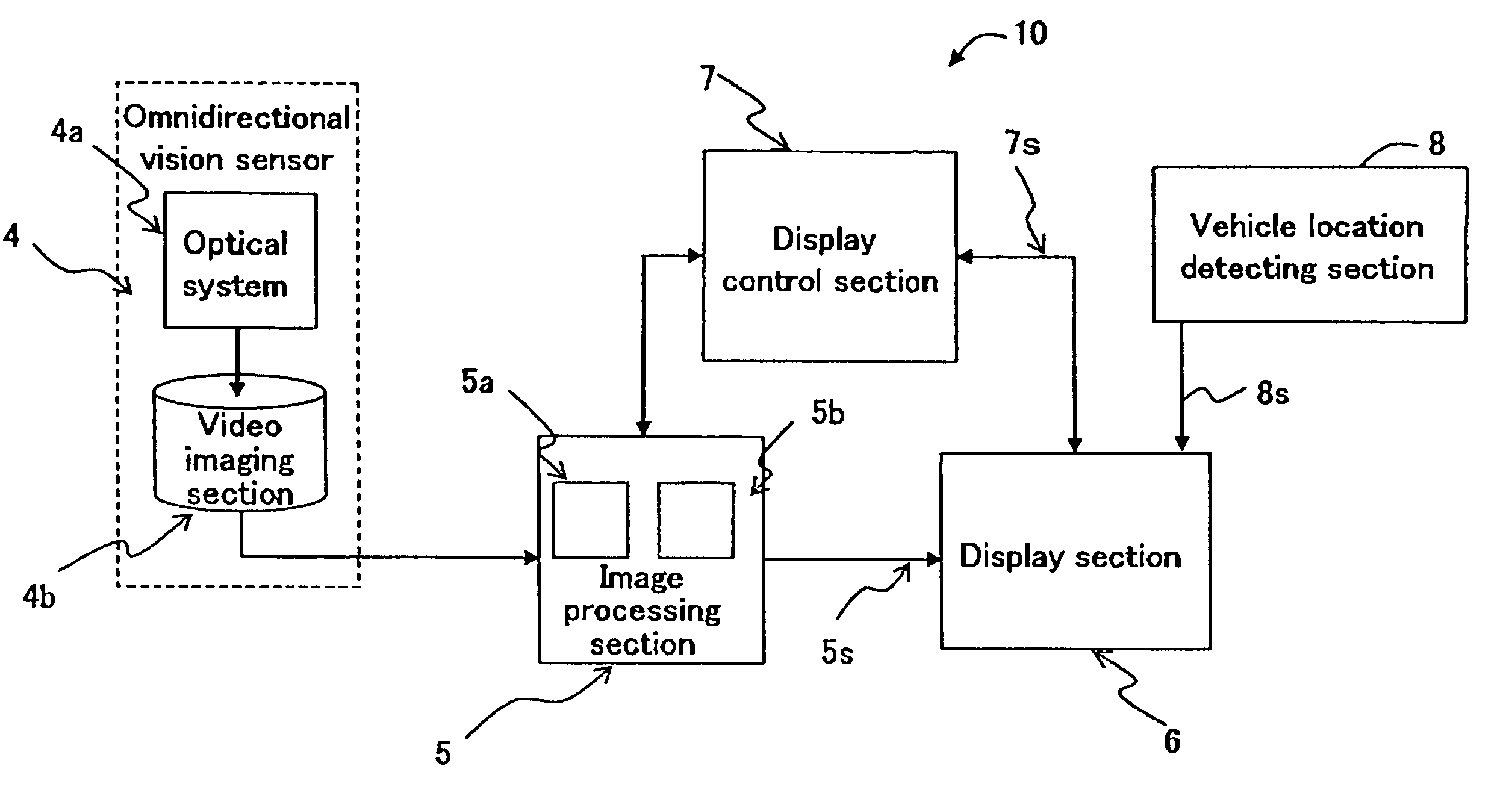
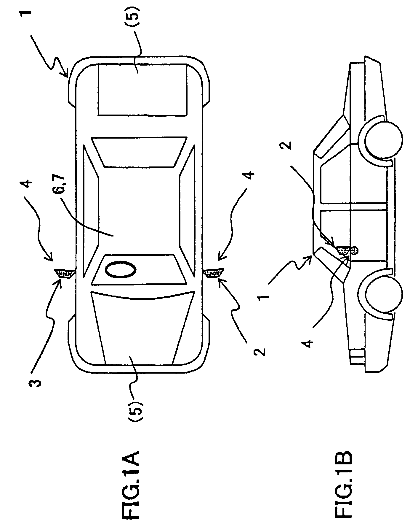
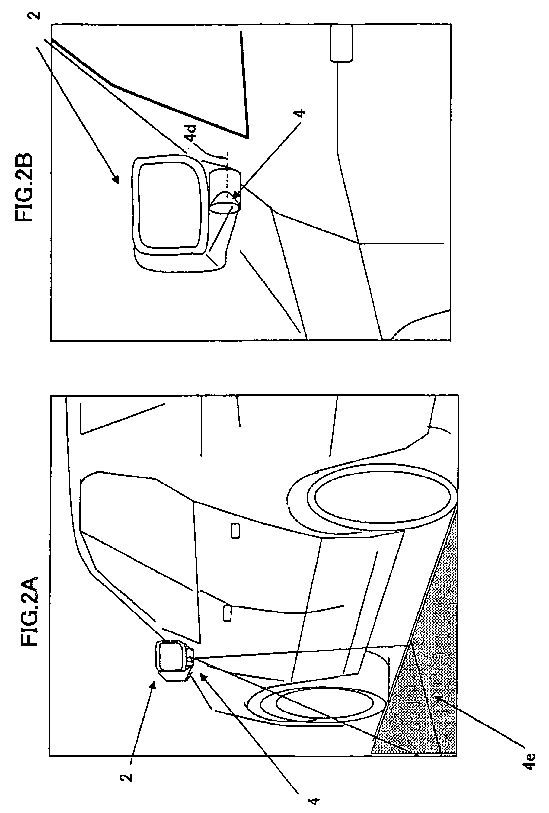
[0057]FIG. 1A is a top view showing a passenger vehicle carrying a vehicle surrounding surveillance apparatus according to an embodiment of the present invention. FIG. 1 is a side view thereof. FIG. 2A is a diagram showing an omnidirectional vision sensor according to an embodiment of the present invention which is attached to a lower portion of the outside rearview mirror of FIGS. 1A and 1B. FIG. 2B is a partially enlarged view of FIG. 2A.

[0058]Referring to FIGS. 1A, 1B, 2A and 2B, the omnidirectional vision sensor 4 is provided at a lower portion of each of left- and right-hand door mirrors 2 and 3 (outside rearview mirrors) of the vehicle (passenger vehicle) 1 with an optical axis 4d (FIG. 2B) of the omnidirectional vision sensor 4 being h...


PUM


Abstract

A mobile body surrounding surveillance apparatus is provided which comprises an omnidirectional vision sensor comprising an optical system for reflecting light incident from a maximum surrounding 360-degree visual field area toward a predetermined direction and an imaging section for imaging light reflected from the optical system to obtain image data, an image processing section for processing the image data obtained by the imaging section, and a display section for displaying the image data processed by the image processing section on a display screen as a mobile body surrounding image. The omnidirectional vision sensor is provided on at least one of left and right sides of the mobile body with an optical axis of the omnidirectional vision sensor being horizontally oriented.

Description

[0001]This nonprovisional application claims priority under 35 U.S.C. §119(a) on Patent Application No. 2003-431265 filed in Japan on Dec. 25, 2003, the entire contents of which are hereby incorporated by reference.BACKGROUND OF THE INVENTION[0002]1. Field of the Invention[0003]The present invention relates to a surrounding surveillance system for surveillance of surroundings of a mobile body, such as a vehicle for transporting persons or things, and a mobile body carrying the same.[0004]2. Description of the Related Art[0005]A recent increase in traffic accidents raises a significant public concern. Particularly, accidents caused by a pedestrian walking against traffic, angle crash of vehicles, rear-end crash of vehicles and the like frequently occur at intersections, such as Y-junction, crossroad and the like. A cause of traffic accidents occurring at such intersections is considered to be that both vehicle drivers and pedestrians have a narrow view compared to that required for c...

Claims


Application Information

Patent Timeline
Patent Type & Authority Patents(United States)
IPC IPC(8): B60Q1/00B60R1/00B60R11/04B60R1/06H04N7/18
CPCB60R1/00B60R2001/1253B60R2300/102B60R2300/806B60R2300/207B60R2300/30B60R2300/802B60R2300/105
Inventor KUMATA, KIYOSHIKITAGAWA, KIYOKAZU
Owner SHARP KK
Why Eureka
Try Eureka