Energy efficient electric water heater system that provides immediate hot water at a point of use and a method therefor

a water heater and energy-efficient technology, applied in the field of plumbing systems, can solve the problems of a substantial interval of time required before the discharge of water, the water heater is located a considerable distance, and the previously heated water sits, so as to achieve the effect of improving the energy-efficient water heater system

a water heater and energy-efficient technology, applied in the field of plumbing systems, can solve the problems of a substantial interval of time required before the discharge of water, the water heater is located a considerable distance, and the previously heated water sits, so as to achieve the effect of improving the energy-efficient water heater system

US7190894B2Inactive Publication Date: 2007-03-13MC3 TECH

Image

  • Energy efficient electric water heater system that provides immediate hot water at a point of use and a method therefor
  • Energy efficient electric water heater system that provides immediate hot water at a point of use and a method therefor

Examples


Embodiment Construction

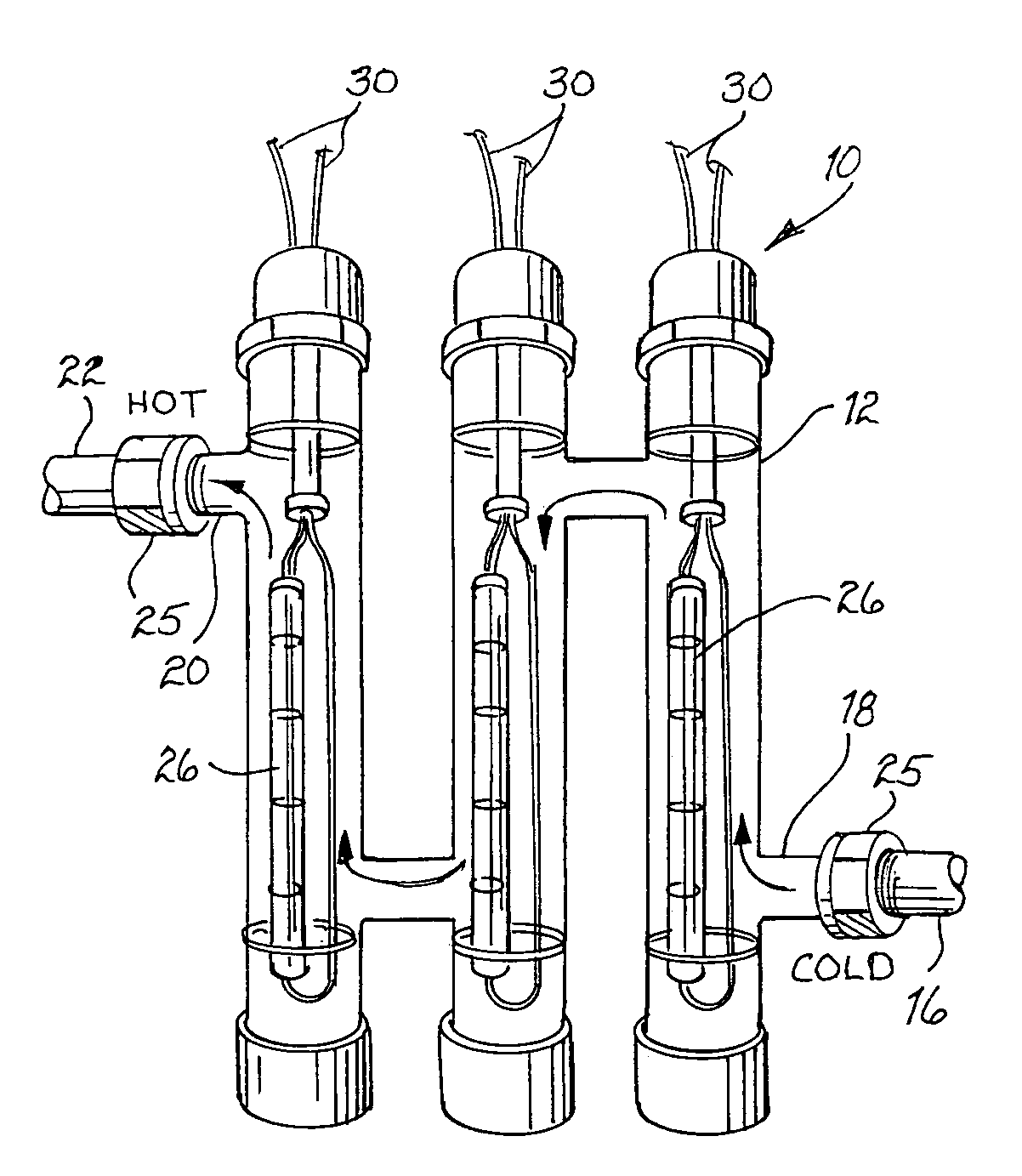
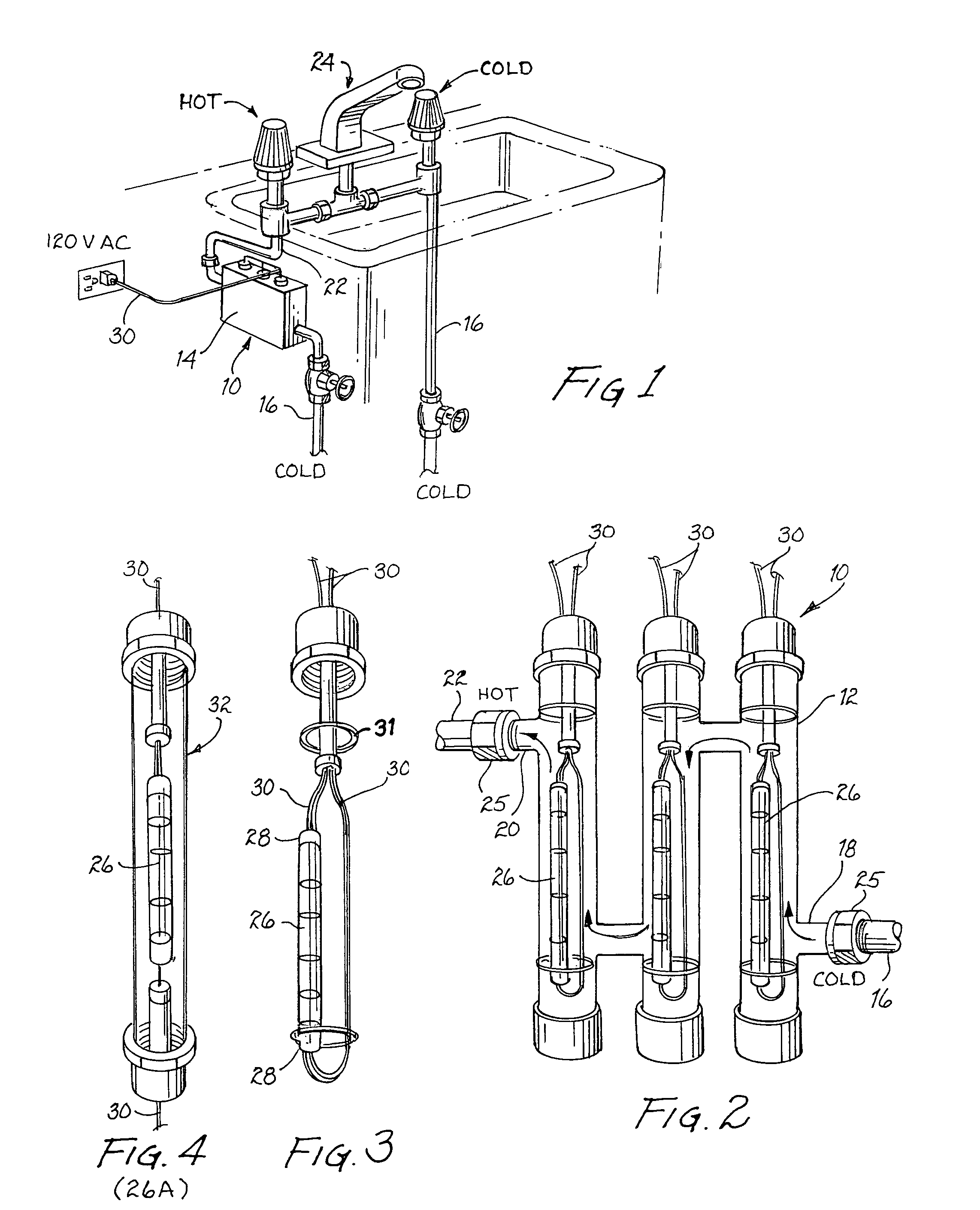
[0014]In accordance with one embodiment of the present invention a water heater system that will provide immediate hot water to a point of use is disclosed. The water heater system has a water storage container having an inlet coupled to a input water pipe and an outlet coupled to a point of use fixture. At least one low current heating element is located within the water storage container and is used to immediately heat water stored within and flowing through the water storage container.

[0015]In accordance with another embodiment of the present invention, a water heater system that will provide immediate hot water to a point of use is disclosed. The water heater system has a water storage container having an inlet coupled to a inlet water pipe and an outlet coupled to a point of use fixture. A low current heating element is located within the water storage container which heats up and removes contaminants in the water stored within and flows through the water storage container. The...


PUM


Abstract

A water heater system that will provided immediate hot water to a point of use has a water storage container having an inlet coupled to a water pipe and an outlet coupled to a point of use fixture. A low current heating element is located within the water storage container and is used to immediately heat up and removes contaminants in the water stored and flowing through the water storage container.

Description

BACKGROUND OF THE INVENTION[0001]1. Field of the Invention[0002]This invention relates to plumbing systems and, more specifically, to an improved energy efficient electric water that will provide immediate hot water to the location or locations to which the hot water is to be delivered.[0003]2. Description of the Prior Art[0004]It is generally a standard practice to provide buildings and residential homes and units with hot water plumbing systems to supply bathrooms, kitchens, and the like with hot water. The hot water plumbing system generally has a water heater which will store 20 gallons or more of water. In order to heat the water in the water heater, various types of NiChrome or other metallic heating elements are installed in the water heater. To provide continuous hot water, the water heater typically operates twenty-four hours a day, unless some type of timer is used. This requires copious amounts of energy in order to accomplish this task. This is due to the fact that the w...

Claims


Application Information

Patent Timeline
13 Mar 2007
Publication
US7190894B2
IPC
F24H1/10; F24D17/00; F24H1/20; H05B3/78
CPC
F24D17/00; H05B3/78; F24H1/202; F24H1/102
Inventors
CHAMBERLAIN, JR., ROLAND J.