Oscilloscope having advanced triggering capability

a technology of advanced triggering and oscilloscope, which is applied in the field of advanced triggering system, can solve the problems of clock-based logic analyzer triggering, inability to produce a stable display of the waveform of interest, and inability to trigger continuously

Active Publication Date: 2007-03-13
TEKTRONIX INC
View PDF9 Cites 58 Cited by
  • Summary
  • Abstract
  • Description
  • Claims
  • Application Information

AI Technical Summary

Problems solved by technology

The earliest oscilloscopes had no triggering capability, and as a result were unable to produce a stable display of the waveform of interest.
However, logic analyzer triggering is clock-based, not continuous.
Moreover, logic analyzers do not respond to “analog” triggers (i.e., those that require comparison to at least two thresholds, such as, rise time, fall time, window, runt, etc.).
Finally, logic analyzers do not employ coupling modes other than DC coupling.
Unfortunately, even a DSO with all of the above-recited triggering functions cannot trigger on certain compound events as found in today's ever more complex circuitry.

Method used


Image

  • Oscilloscope having advanced triggering capability
  • Oscilloscope having advanced triggering capability
  • Oscilloscope having advanced triggering capability

Examples


Embodiment Construction

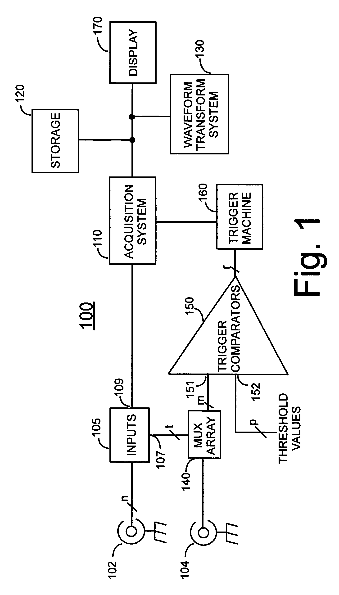
[0021]FIG. 1 shows a high-level block diagram of a digital storage oscilloscope (DSO) 100 according to the subject invention. Oscilloscope 100 includes an input 102 for receiving a signal under test (SUT) from a user's circuit. Although shown as a single connector for simplicity, input 102 actually comprises a number n of input channels (where n is any reasonable number, but usually 1, 2, 4 or 8). The n signal lines are applied to an input block 105 representing the “front end” of the oscilloscope including, buffer amplifiers, attenuation circuitry, and the like for conditioning the input signal. Input block 105 has a first output I for providing signals over a number of lines t to a first input of a Multiplexer (Mux) Array unit 140, and a second output terminal 109 for providing the conditioned input signal to an Acquisition System 110 wherein signal samples are taken repeatedly, are converted to digital form, and are stored in a circular acquisition memory. Mux Array 140 has a sec...


PUM


Abstract

An advanced trigger circuit includes two trigger decoders, each triggering on one of respective pluralities of continuous-time trigger events. In one embodiment, a programmable timer begins timing in response to an output signal of the first trigger decoder and generates an end-of-time signal at the expiration of its time period. A reset circuit resets the first trigger decoder if the second selected continuous-time trigger event failed to occur before the end-of-time signal was generated. In another embodiment, a reset decoder generates a reset signal in response to an occurrence of a selected continuous-time trigger event. The reset circuit is responsive to the reset signal for resetting the first trigger decoder if the second selected continuous-time trigger event failed to occur before the reset signal was generated. In other embodiments, the advanced trigger circuit triggers on a serial lane skew violation or on a beacon width violation.

Description

CLAIM FOR PRIORITY[0001]The subject application claims priority from U.S. Provisional Patent Application Ser. No. 60 / 555,900 ADVANCED TRIGGERING (Smith, et al.) filed 23 Mar. 2004, and from U.S. Provisional Patent Application Ser. No. 60 / 555,892 SERIAL LANE SKEW VIOLATION TRIGGER FOR AN OSCILLOSCOPE (Tran, et al.) filed 23 Mar. 2004, and from U.S. Provisional Patent Application Ser. No. 60 / 555,899 SERIAL BEACON WIDTH VIOLATION TRIGGER (Tran, et al.) filed 23 Mar. 2004, all assigned to the same assignee as the subject application.FIELD OF THE INVENTION[0002]The subject invention generally relates to the field of triggered oscilloscopes, and specifically concerns an advanced trigger system for a modern digital oscilloscope.BACKGROUND OF THE INVENTION[0003]An oscilloscope is an electronics test and measurement instrument used by an engineer to acquire and display a waveform of interest from a particular test point of a circuit under test. The earliest oscilloscopes had no triggering ca...

Claims


Application Information

Patent Timeline
Patent Type & Authority Patents(United States)
IPC IPC(8): G01R13/00G01R13/02G01R13/20G01R13/32
CPCG01R13/32G01R13/0254
Inventor SMITH, PATRICK A.TRAN, QUE THUYDELACY, JOHN C.KNIERIM, DANIEL G.KELLY, DAVID L.CALVIN, JOHN C.
Owner TEKTRONIX INC
Why Eureka
Try Eureka