
Method using embedded real-time analysis components with corresponding real-time operating system software objects

Active Publication Date: 2007-03-13
TEXAS INSTR INC
View PDF7 Cites 20 Cited by
  • Summary
  • Abstract
  • Description
  • Claims
  • Application Information

AI Technical Summary

Benefits of technology

[0012]An advantage of OSs according to the example embodiment is that they provide hardware support for functions such as stack overflow detection, real-time task priority modification, and / or system scheduling error assertion. A device which utilizes an OS according to the example embodiment can therefore provide a higher level of service. For example, such an OS makes it possible to capture events that would otherwise be non-detectable or require additional software content and CPU use. Another advantage is that the example embodiment can perform functions for the real-time operating system without taking consuming valuable processing time from that real-time operating system, thus allowing the device to accomplish more processing within the allotted time.

Problems solved by technology

Certain data processing jobs require large amounts of mathematical processing and specialized digital signal processing algorithms.
The challenges faced by developers of real-time programs include challenges relating to program verification and troubleshooting.
Intrusion may be in terms of space, in that the techniques for debugging the program may take up memory space, or in terms of time, in that the steps required for debugging the program may consume cycles in the DSP's central processing unit (i.e., the CPU core).
A disadvantage associated with traditional tools for real-time analysis is that they interfere with the programs being analyzed by consuming cycles in the CPU core and occupy system memory space.

Method used


Image

  • Method using embedded real-time analysis components with corresponding real-time operating system software objects
  • Method using embedded real-time analysis components with corresponding real-time operating system software objects
  • Method using embedded real-time analysis components with corresponding real-time operating system software objects

Examples


Embodiment Construction

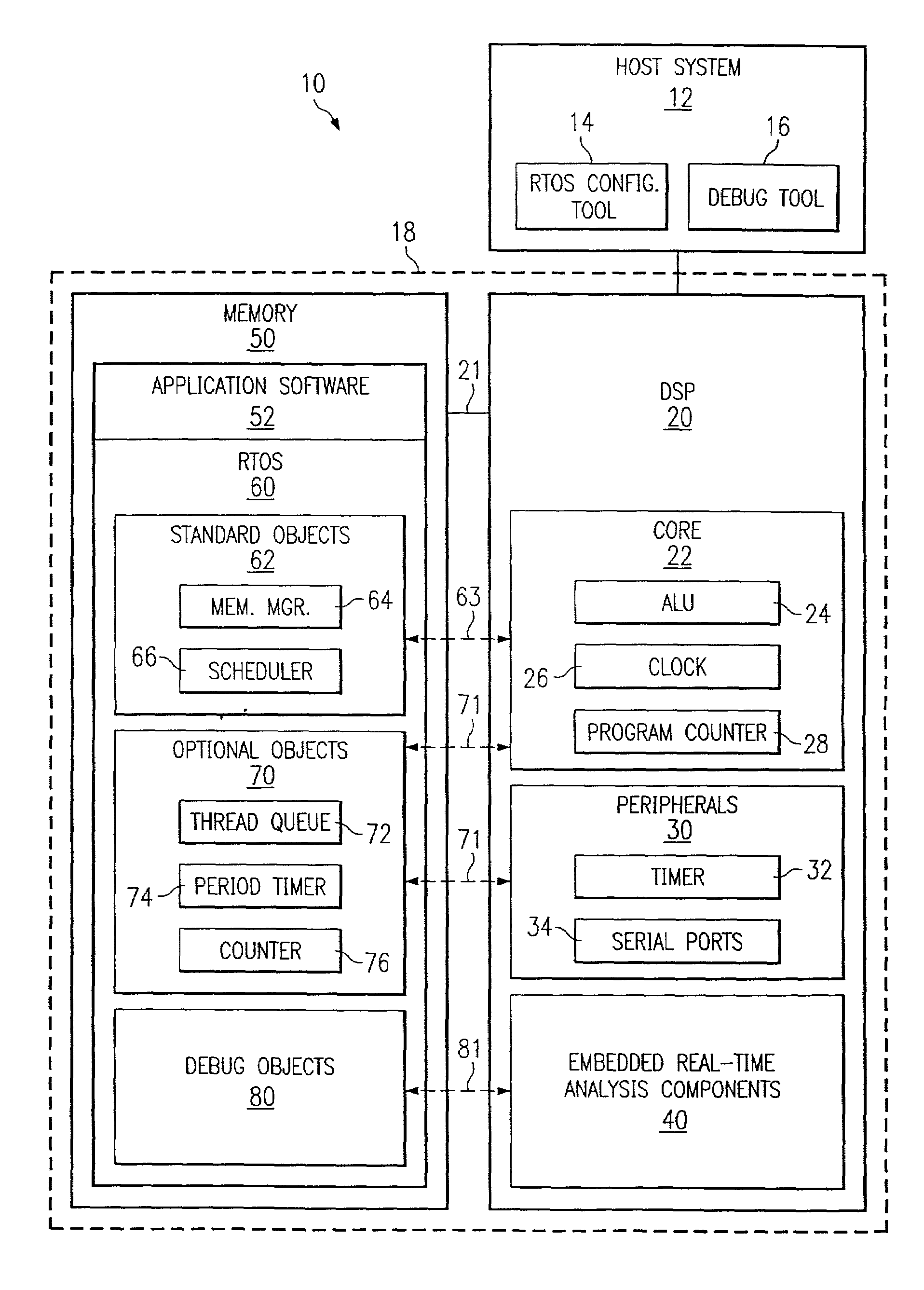
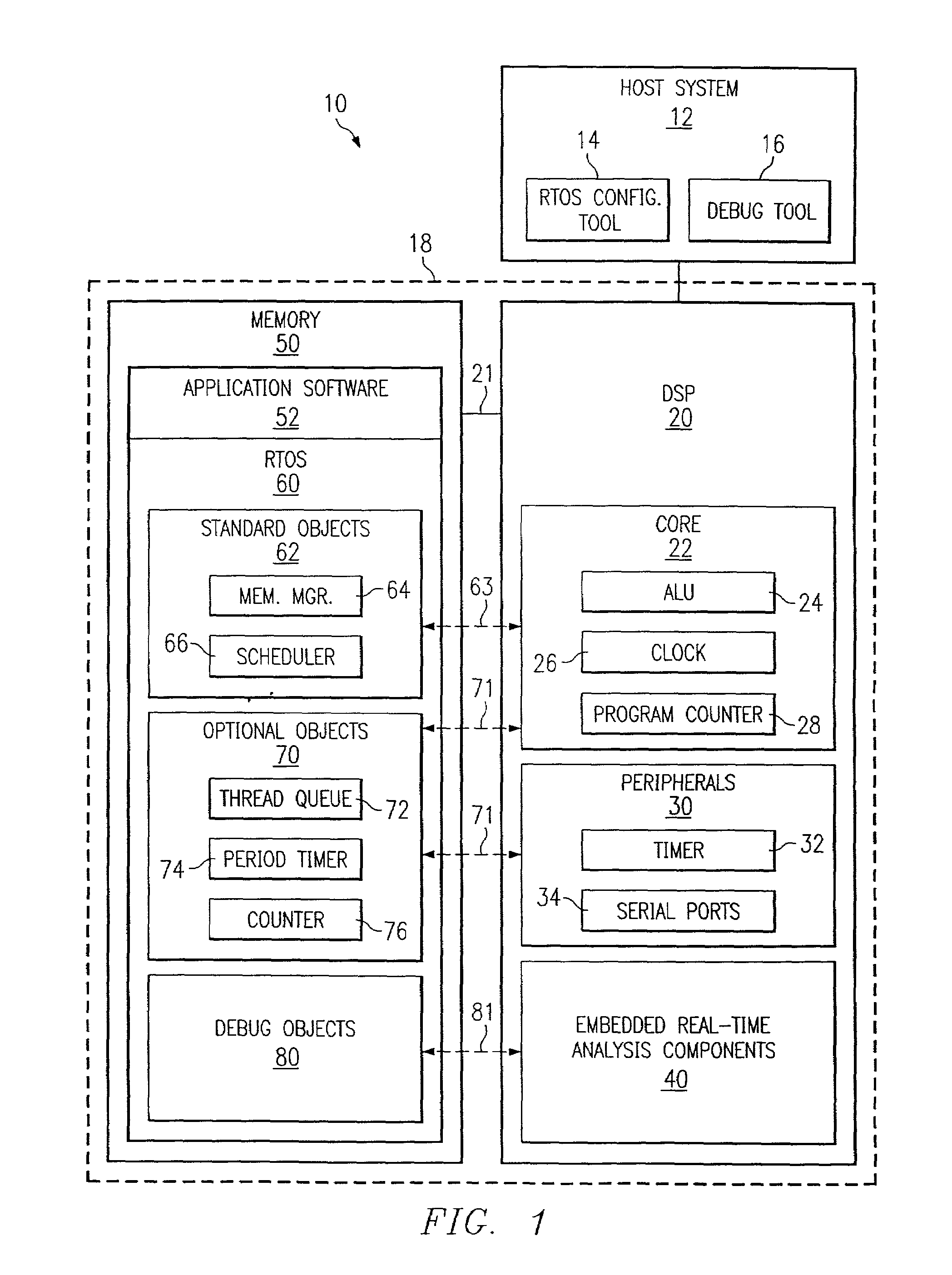
[0018]FIG. 1 shows an example development system 10 with a host system 12 connected to a data processing device 18. Host system 12, which may be a PC, is used to develop real-time applications or programs, such as application software 52, for data processing device 18. Accordingly, host system 12 includes a real-time application debug tool 16 for verifying proper operation and troubleshooting the hardware and software of data processing device 18.

[0019]In the example embodiment, data processing device 18 includes various hardware components, including a memory 50, a DSP 20, and a bus 21 that connects DSP 20 and memory 50. DSP 20 is an integrated circuit with many embedded modules, including a CPU core 22 with components such as a program counter 28, one or more arithmetic logic units (ALUs) 24, and one or more clocks 26. Various peripherals 30, such as timers 32 and serial ports 34, are also embedded in DSP 20. These peripherals could also include, but are not limited to, DMAs, Cach...


PUM


Abstract

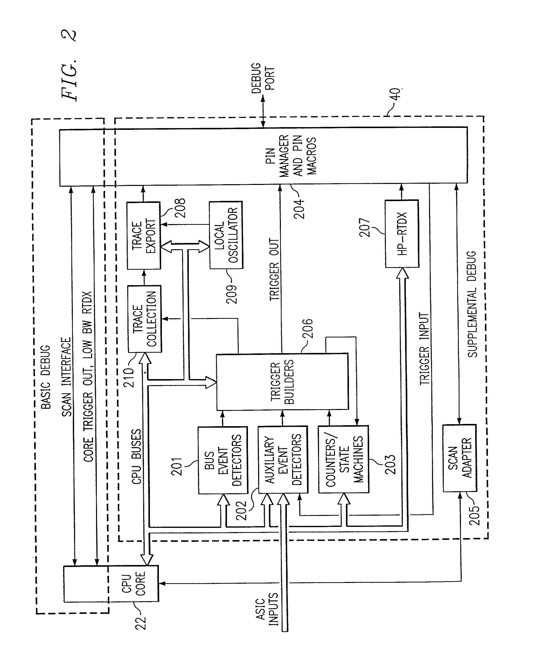
An operating system (OS) is used in a system with a processor that includes embedded real-time analysis components. The OS includes software objects which provide functionality in response to signals from the embedded real-time analysis components. In an example embodiment, the OS is a real-time OS (RTOS), the embedded real-time analysis components include an embedded event trigger component, and the software objects include a debug object that responds to signals from the embedded event trigger component. For instance, those signals may relate to program flow, data flow, or a hardware operation such as a cache miss, and the debug object may be a breakpoint handler, a trace handler, or an event sequence handler. In the example embodiment, the software objects in the RTOS provide functionality such as stack overflow detection, real-time task priority modification, and / or system scheduling error assertion for a real-time application. Alternative embodiments involve related methods and systems.

Description

[0001]This application claims priority under 35 USC §(e)(1) of Provisional Application No. 60 / 316,524, filed Aug. 31, 2001.CROSS REFERENCE TO RELATED APPLICATION [0002]Copending U.S. patent application Ser. No. 09 / 798,173, entitled “System and Method for Automatically Configuring a Debug System,” now U.S. Pat. No. 6,785,850, assigned to the assignee of the present application, is hereby incorporated herein by reference.TECHNICAL FIELD OF THE INVENTION[0003]This invention relates in general to data processing systems. In particular, this invention relates to systems and methods for using embedded real-time analysis components of processors such as digital signal processors.BACKGROUND OF THE INVENTION[0004]Computer operating systems are resident on nearly every computer and are typically required to run application software. Certain data processing jobs require large amounts of mathematical processing and specialized digital signal processing algorithms. Processing hardware units know...

Claims


Application Information

Patent Timeline
IPC IPC(8): G06F9/46G06F11/00G06F9/44G06F11/36
CPCG06F11/362
Inventor BROKISH, CHARLES W.
Owner TEXAS INSTR INC
Learn More