Structural prefabricated column post for securing to the ground

a prefabricated, column technology, applied in the field of columns, can solve the problems of cost and time-consuming construction

Inactive Publication Date: 2007-03-20
NEWTON II WILLIAM DANIEL
View PDF14 Cites 32 Cited by
  • Summary
  • Abstract
  • Description
  • Claims
  • Application Information

AI Technical Summary

Benefits of technology

[0010]A notched plastic angle member is pre-attached to the bottom of the column that will serve three functions: it will provide an upper edge for leveling the concrete within the concrete form, it serves to protect the column from the caustic base, and the notched areas will provide air gaps at the bottom of the column to allow air to circulate through the interior of the column. Each of the support pans are provided with openings in them to allow for air circulation within and through the column. The openings in the support pans also provide access to help in the insertion of the central tube through the support pans. Also, spacer tabs are provided at the top of the column to hold the top of the column off of the side walls to form an air gap at the top of the column so that air can flow freely through the entire height of the column. Because the column may be constructed either completely or partially of metal, it is important to have air circulation within the column to prevent the accumulation of moisture and rusting inside the column.

Problems solved by technology

Currently estate-type columns are generally constructed of brick, concrete, or wood and are costly and time consuming to construct.

Method used


Image

  • Structural prefabricated column post for securing to the ground
  • Structural prefabricated column post for securing to the ground
  • Structural prefabricated column post for securing to the ground

Examples


Embodiment Construction

The Invention

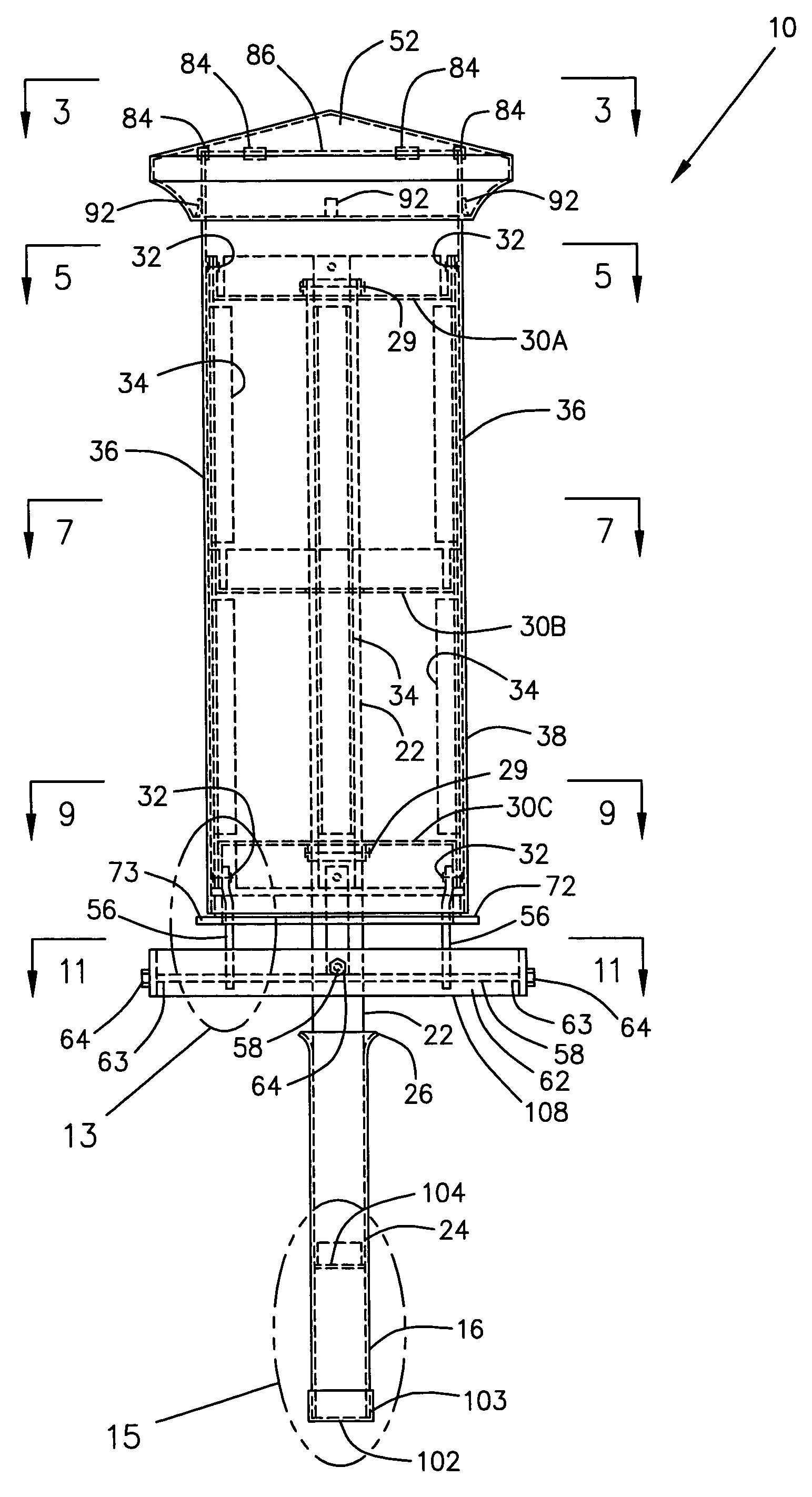
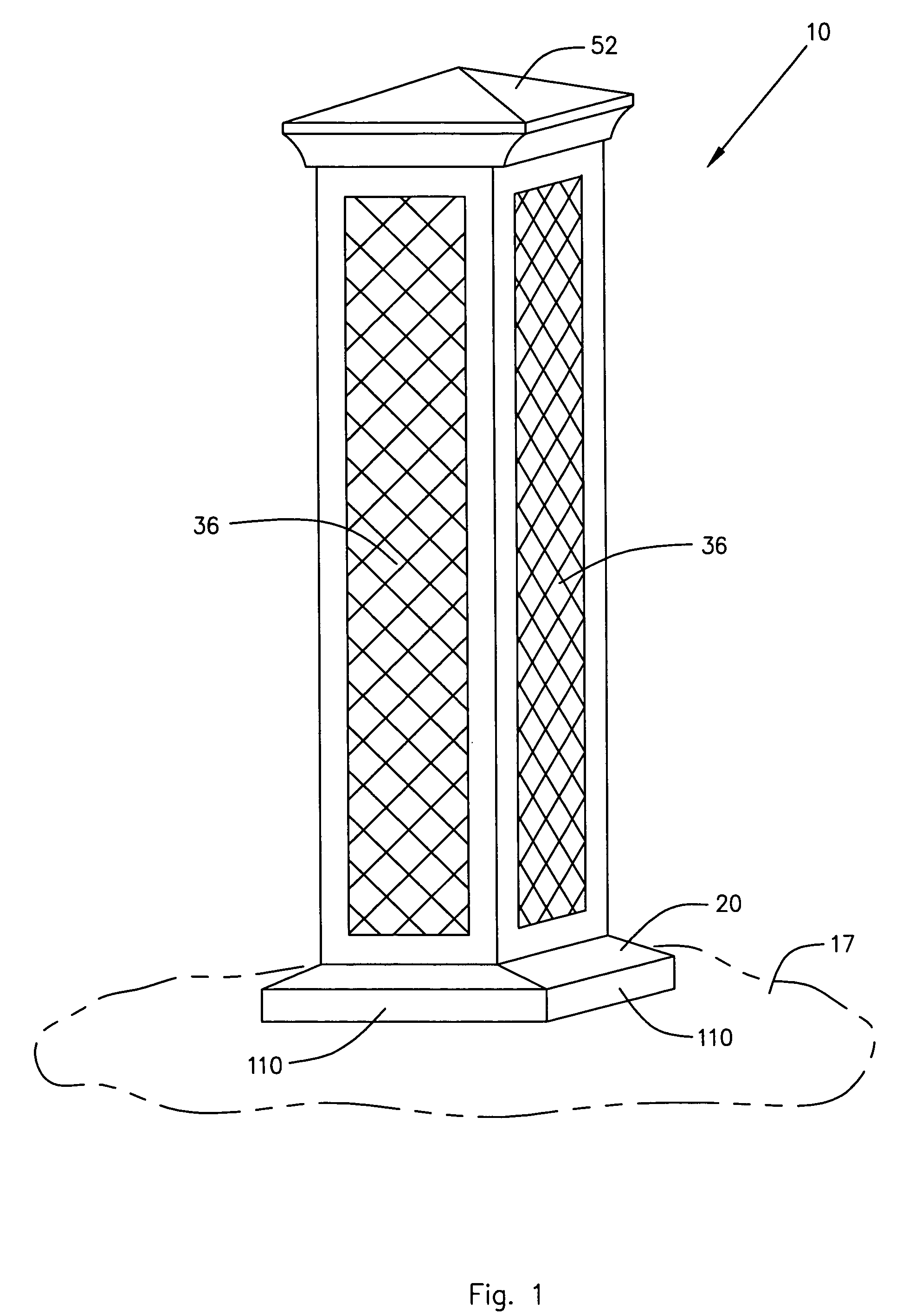
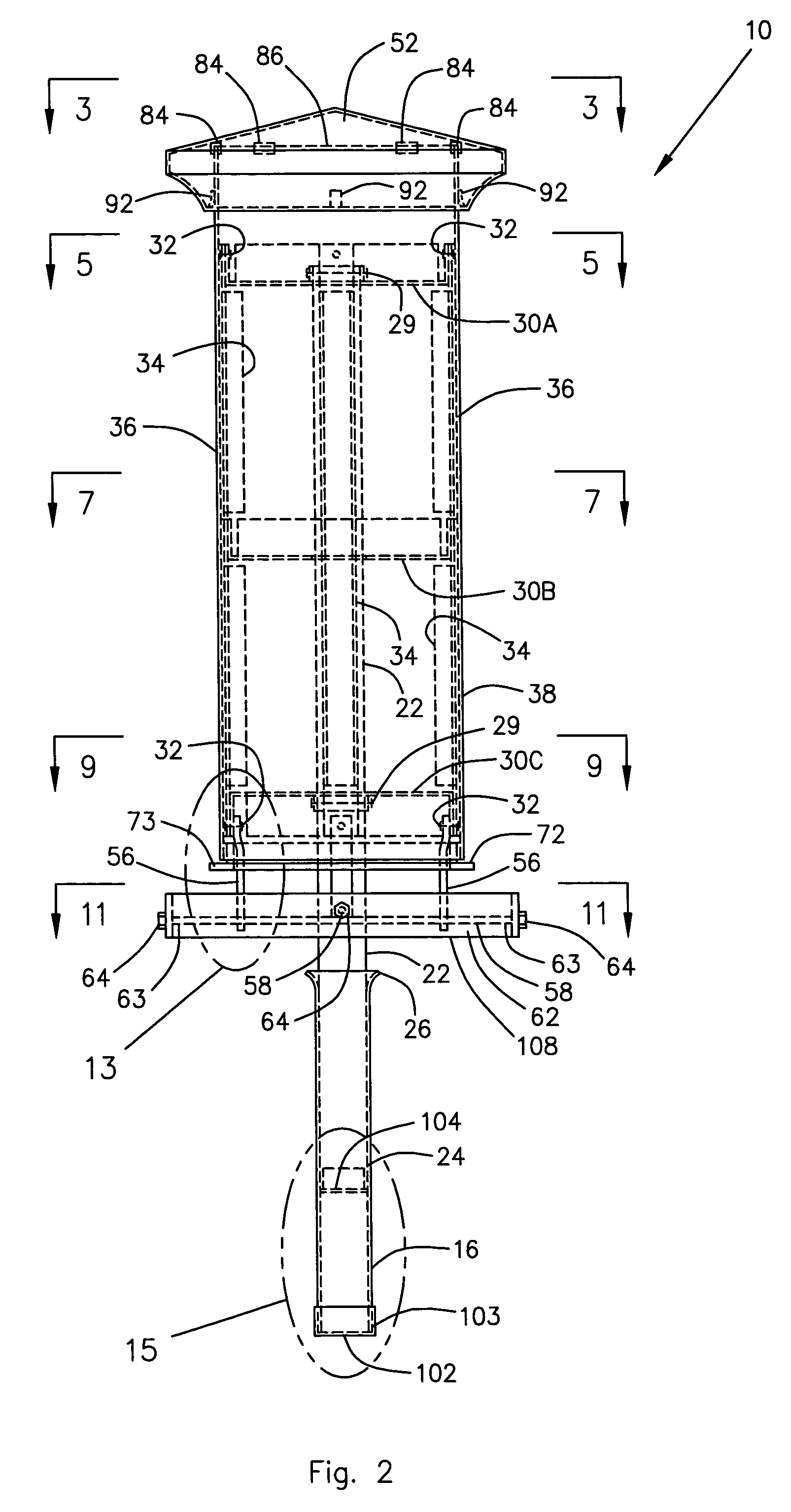
[0045]Referring now to the drawings and initially to FIGS. 1 and 2, there is illustrated a column 10 constructed in accordance with a preferred embodiment of the present invention. The column 10 is partially prefabricated so that a homeowner or contractor can install the column 10 employing a minimum of time, tools, money, and effort.

[0046]First, as illustrated in FIG. 23, a hole 12 is dug in the ground 14 with the hole 12 being sufficiently large and deep to allow a receiver tube 16 to be secured at the proper elevation relative to ground level 17, per the column manufacturer's instructions for installation. The receiver tube 16 of FIGS. 23–25 is shown installed with the flared upper end 24 of the receiver tube 16 located approximately two inches below ground level 17, although the invention is not limited to this exact depth. At the same time that the hole 12 is dug in the ground 14, a flattened area 18 is formed in the ground level 17 surrounding the hole 12 as a pla...


PUM


Abstract

A partially prefabricated column. The column has vented support pans and vertical ribs internally. Skin attaches to the vertical ribs. Rods secure to the bottom of the column and a concrete form is removably secured to the rods. Air gaps at the top and bottom of the column allow for air circulation through the column. A top attaches over the upper end of the column. A central tube is secured to the column via the support pans and is telescopically received within a receiver tube concreted into the ground. The column gently descends to the ground as the central tube inserts into the receiver tube. Concrete is then poured into the concrete form and the concrete troweled between a notched plastic angle member on the bottom of the column and the concrete form. The concrete cures, the form is removed and the ends of the rods are plugged.

Description

BACKGROUND OF THE INVENTION[0001]1. Field of the Invention[0002]The present invention relates to a column that is partially prefabricated so that a homeowner or contractor can install the column to achieve professional looking results while employing a minimum of time, tools, money, and effort. The column can be used for a variety of purposes, including use for a fence, trellis, arbor, or porch support or as a supporting column for a mailbox.[0003]The column is provided with a central tube and with Z-shaped tabs that secure the column to rods. The central tube and the rods are employed to secure the column to a receiver tube concreted into ground. The column is also provided internally with horizontal support pans that secure to the central tube and with vertical ribs that secure to the support pans to form the internal structural support for the column. A skin of metal or other suitable material secures to the vertical ribs with double sided tape. The skin can be formed in patterns...

Claims


Application Information

Patent Timeline
Patent Type & Authority Patents(United States)
IPC IPC(8): E04C3/30
CPCE04H12/2253
Inventor NEWTON, II, WILLIAM DANIEL
Owner NEWTON II WILLIAM DANIEL
Why Eureka
Try Eureka