
Method and apparatus for connecting and disconnecting threaded tubulars

a technology of threaded tubulars and connecting devices, which is applied in the direction of wrenches, drilling pipes, drilling casings, etc., can solve the problem of small amount of further rotation and need to be rotated

Active Publication Date: 2007-03-20
FRANKS INT
View PDF24 Cites 67 Cited by
  • Summary
  • Abstract
  • Description
  • Claims
  • Application Information

AI Technical Summary

Benefits of technology

[0009]A backup tong prevents the stump, or proximal end of the tubular string, from rotating during the application of torque by the spinner-wrench to the tubular segment being added to the tubular string. Optionally, the backup tong may be operated manually, pneumatically or hydraulically. The backup tong may be secured using a backup snubline to a fixed structure to oppose the torque of the spinner-wrench, or it may be rotatably coupled to the spinner-wrench to form an integral structure. In the latter configuration, the spinner-wrench grips and rotates the tubular segment being added to the tubular string at a location just above the threaded portion, while the backup tong holds the tubular string at a location just below the threaded portion. The backup tong holds the tubular string stationary against the torque applied to the tubular segment and also secures the arms of the spinner-wrench for application of torque to the tubular segment. Where a fixed structure is used to secure the backup tong, the backup snubline and the second displacer may have one end secured to the same fixed structure, such as a snub post. The spinner-wrench apparatus, with or without an integral backup tong, may be configured so that the torque applied by the second displacer is rotationally directed to makeup the tubular or rotationally directed to break out the tubular.

Problems solved by technology

Consequently, the process of threadably connecting tubulars is an important part of wellbore operations and utilizes a significant amount of time and equipment.
However, once the tubulars are shouldered, only a small amount of further rotation is necessary to complete the connection.

Method used


Image

  • Method and apparatus for connecting and disconnecting threaded tubulars
  • Method and apparatus for connecting and disconnecting threaded tubulars
  • Method and apparatus for connecting and disconnecting threaded tubulars

Examples


Embodiment Construction

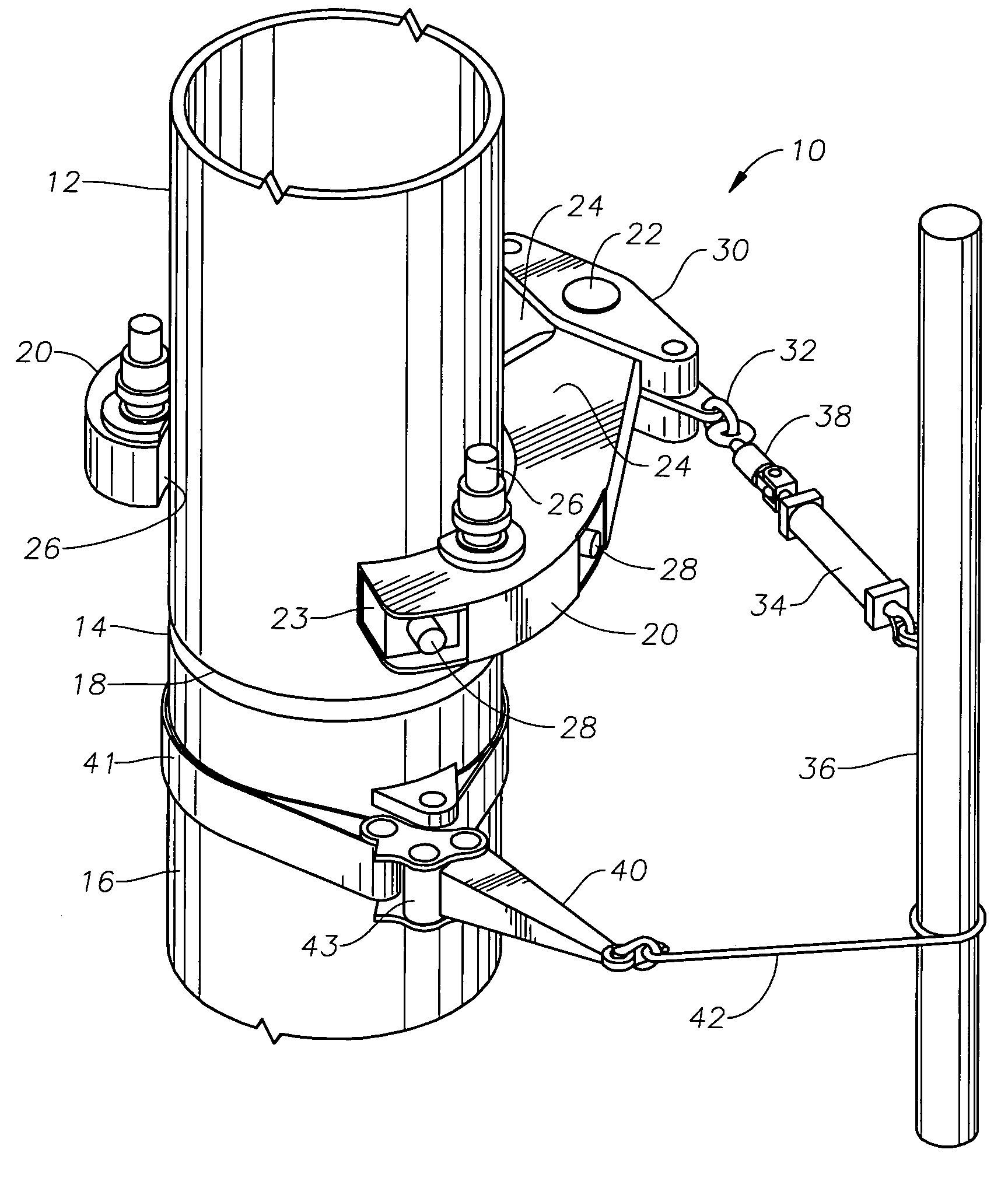
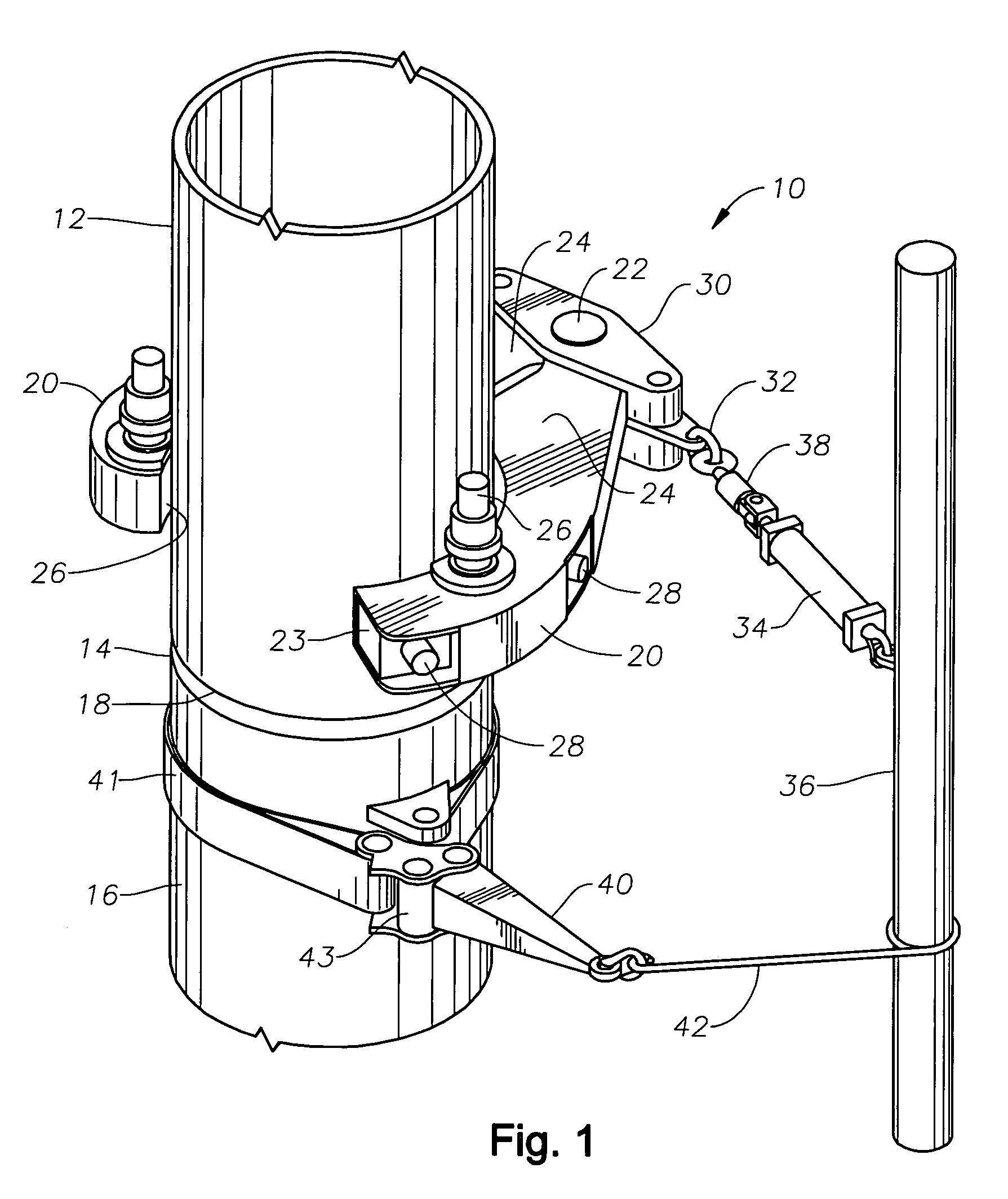
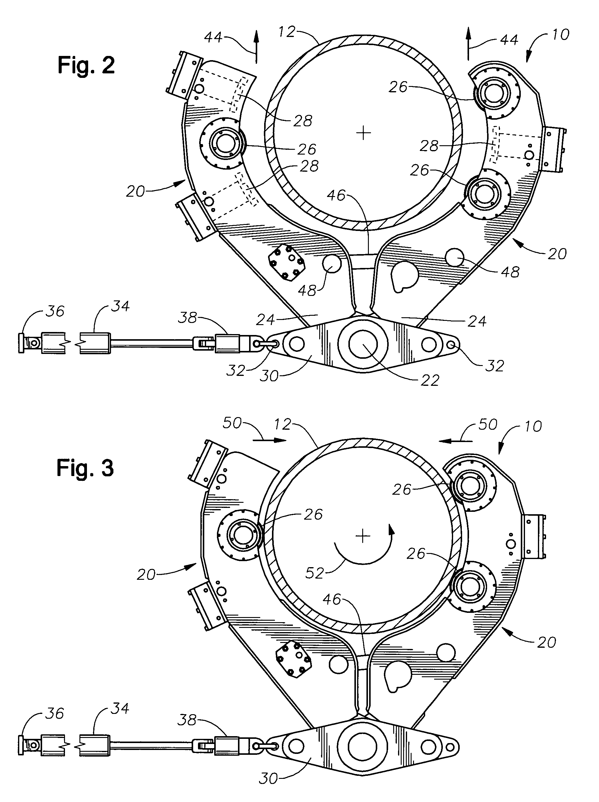
[0023]FIG. 1 is a perspective view of one embodiment of an apparatus for connecting threaded tubulars. The apparatus 10 is shown engaging a tubular 12 above a downwardly directed threaded pin 14 that is to be connected to a tubular string 16 having an upwardly directed threaded box 18. The tubular string 16 extends axially downward into the wellbore and the tubular 12 is suspended by a lift elevator (not shown) and positioned in axial alignment with the tubular string 16 to facilitate the connection. The apparatus 10 operates in a generally horizontal plane that is perpendicular to the axis of the tubular 12. The apparatus 10 includes a pair of arms 20 that are hingedly coupled by a hinge pin 22 at their distal ends 24. The pair of arms 20 forms an opening between the proximal ends 23 of the arms to receive the tubular 12. Collectively, the pair of arms 20 includes three or more rollers 26 and two or more jaws 28 (See also FIG. 2). Preferably, there are three or more rollers 26 span...


PUM


Abstract

A system for screwing together threaded connections includes a pair of moveable arms which first grip the tubular to provide a contact force against three hydraulically powered drive rollers, that are contained within the arms. The three drive rollers will screw or “spin” the connection to an initial torque value. The moveable arms also contain a set of jaws (three) which extend radially inwardly to grip the tubular, so the connection can be made up to final torque by contracting a hydraulic cylinder. The hydraulic cylinder that is used to apply the final torque value is attached on one end, where the moveable arms are pinned together, and on the other end to something fixed, such a snub post or derrick leg. Rotation of the opposing connection is prevented by the use of standard equipment such as a manual chain tong.

Description

BACKGROUND OF THE INVENTION[0001]1. Field of the Invention[0002]The present invention relates to a method and apparatus for connecting and disconnecting threaded tubulars to or from a tubular string in a wellbore.[0003]2. Background of the Related Art[0004]The process of drilling and installing casing in a wellbore requires the connection or makeup of many sections of tubulars, such as drill pipe or casing. These sections of tubulars may be individual joints or stands of multiple joints. As a wellbore deepens, more tubulars must be threadably connected onto the string. Consequently, the process of threadably connecting tubulars is an important part of wellbore operations and utilizes a significant amount of time and equipment. Furthermore, a tubular string may need to be removed from the wellbore for a variety of reasons, such as replacing a drill bit or due to cross-threading of casing. Accordingly, disconnection or break out of many tubular sections is also an important part of we...

Claims


Application Information

Patent Timeline
IPC IPC(8): B25B13/50
CPCE21B19/163E21B19/168E21B19/165
Inventor ANGELLE, JEREMY R.MOSING, DONALD E.THIBODEAUX, JR., ROBERT L.PECHON, CHRISTOPHER B.
Owner FRANKS INT
Learn More