Modular gauge block assembly with secure lateral pins

a module and gauge block technology, applied in the direction of embroideries, sewing apparatus, textiles and paper, etc., can solve the problems of reducing the service lifeallowing too much play, and accumulating errors in positioning the gauge elements. , to achieve the effect of reducing the vibration facilitating the operation of the tufting machine, and reducing weigh

Inactive Publication Date: 2007-03-20
TUFTCO
View PDF7 Cites 12 Cited by
  • Summary
  • Abstract
  • Description
  • Claims
  • Application Information

AI Technical Summary

Benefits of technology

[0009]At least the front surface of the block contains a plurality of spaced parallel slots so that gauge elements may be positioned in the slots with proper spacing. The proximal ends of the gauge elements may have apertures or channels recessed therein. In one embodiment of the present invention the proximal ends of the gauge elements are inserted into the block and secured there by a lateral pin that enters the block on one of the opposing side surfaces and passes through apertures on the proximal ends of the gauge elements. One alternative embodiment allows the pin to be placed by forming a channel in the block. Another alternative embodiment biases a lateral pin resting in a channel on the proximal ends of the gauge elements by tightening a securing bolt that is in communication with the lateral pin through an opening on the block. The securing bolts may have conical ends or flat ends depending upon their orientation with respect to the lateral pin to exert a wedging or camming force against the lateral pin. In either case the gauge elements are secured by a lateral pin engaging the gauge elements. Individual gauge elements can be replaced by demounting the affected block, removing the lateral pin and removing a selected gauge element. After the selected gauge element is removed a new gauge element may be re-inserted into the proper vertical slot and secured by the lateral pin and securing bolt.
[0012]Of particular advantage is the use of lightweight aluminum alloys such as aluminum 7075 from which to manufacture modular blocks. When these modules are utilized with aluminum alloy or other lightweight material hook bar brackets, jack shaft rockers, and hook shaft drive levers, approximately 40% of the weight of these components, comprising some 200 pounds across the length of a broad loom tufting machine, can be removed from the moving action of the machine. This reduction in weight tends to correspondingly reduce the vibration of the tufting machine and facilitates operation of the tufting machine at higher speeds.
[0013]Accordingly, it is an object of the present invention to provide a tufting machine where the gauge elements of the tufting machine are accurately positioned within a modular block assembly.
[0014]Another object of the present invention is to provide in a tufting machine, a system which can facilitate the rapid change over of one or more damaged gauge elements, reducing to a minimum the downtime of the tufting machine.
[0015]Another object of the present invention is to provide in a modular block assembly, a system which can facilitate the rapid change over of individual damaged gauge elements, reducing the cost of repairing broken gauge elements and removing the need to replace entire modular blocks when a single gauge element becomes damaged.

Problems solved by technology

When assembling a tufting apparatus, errors in positioning these gauge elements may accumulate as the work progresses.
When the blocks are machined from relatively soft metals such as aluminum, there has been a tendency for the threads of the block to become worn and allow too much play for all of the screws to securely hold their corresponding gauge elements.

Method used


Image

  • Modular gauge block assembly with secure lateral pins
  • Modular gauge block assembly with secure lateral pins
  • Modular gauge block assembly with secure lateral pins

Examples


Embodiment Construction

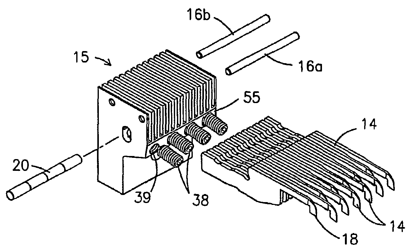
[0058]The present invention is designed for use in tufting machines of the type generally including a needle bar carrying one or more rows of longitudinally spaced needles that are supported and reciprocally driven by a plurality of push rods. In the tufting zone shown in FIG. 23, the needles 13 carry yarns 50 which are driven through a backing fabric 114 by the reciprocation of the needles. While penetrating the backing fabric, a plurality of longitudinally spaced hooks 18, 14 cooperate with the needles to seize loops of yarns and thereby form the face of a resulting fabric. In some cases the hooks will cooperate with knives 113 to cut the loops of yarn seized on the hooks and thereby form a cut pile face 146 for the fabric. The present invention is directed to modular units for holding loopers or hooks and for holding needles to facilitate their cooperation during the tufting process.

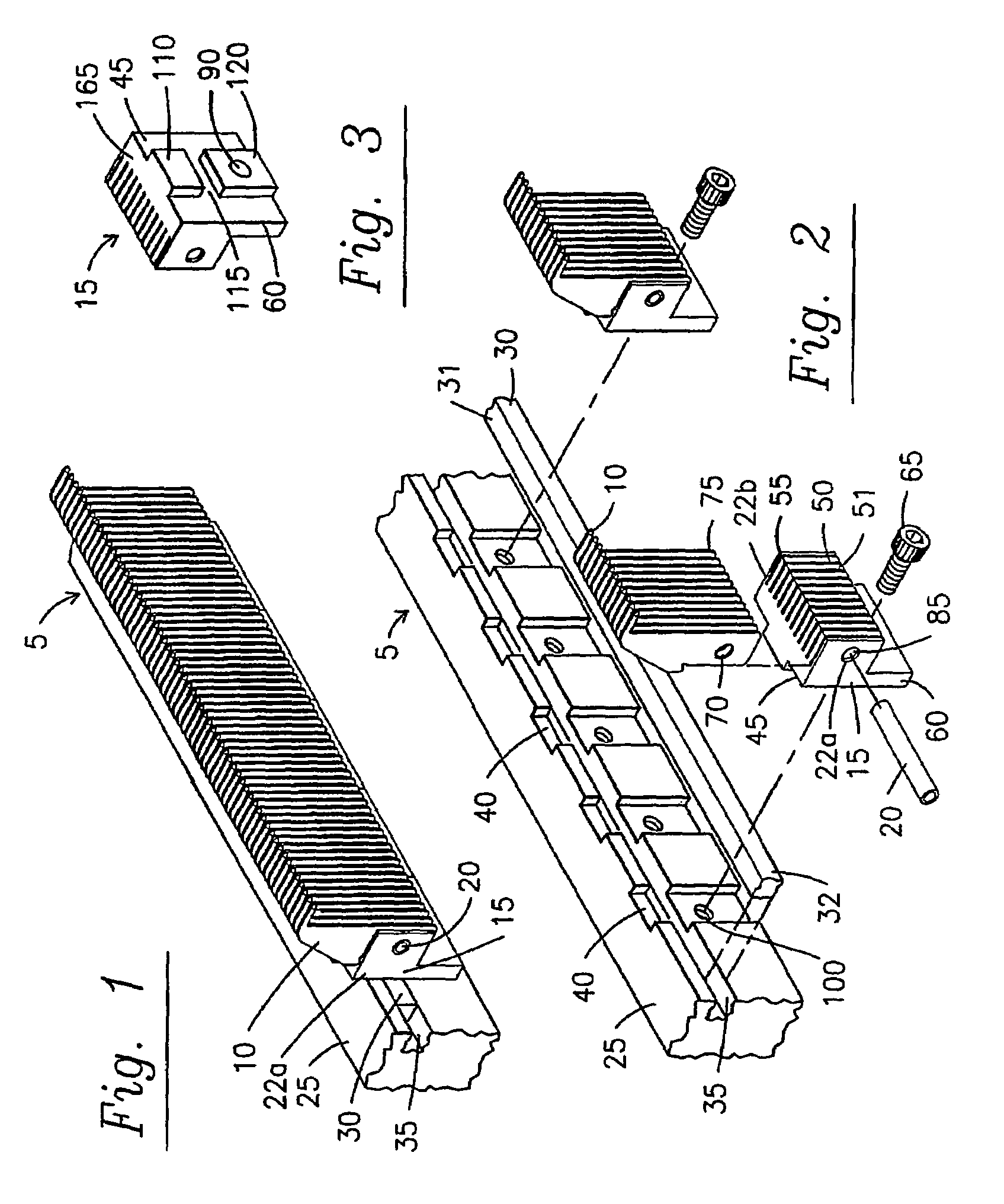
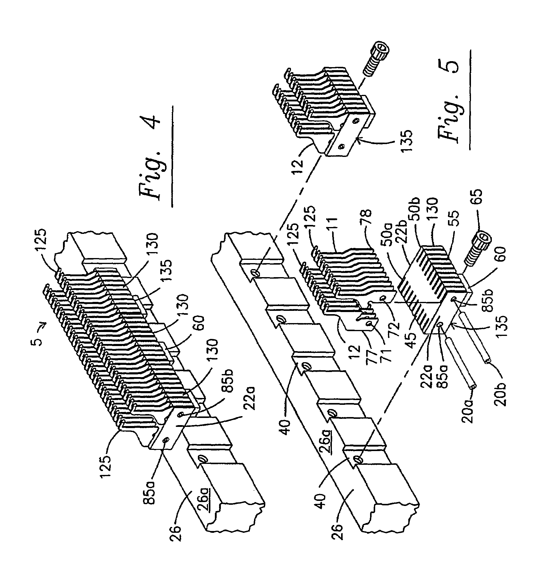
[0059]Referring in detail to FIG. 1, a modular block assembly 5 is illustrated having a single row...


PUM


Abstract

Lateral pins (20) are used to provide a tufting machine modular gauge assembly that allows damaged or broken gauge elements (10) to be replaced individually. The modular gauge assembly consists of a gauge bar (25) with a plurality of modular blocks (15) removably attached to the bar. The modular blocks are six sided with a detent (110) and fastener mechanism (65) for attaching the block to the gauge bar. The gauge elements may be attached to the block by dedicated screw-pins (145) or by a lateral pin (20) that passes through all the gauge elements within a block. The lateral pin may either pierce the gauge elements (at 70) or abut the gauge elements. Abutting pins may be malleable and segmented and secured in position by set screws.

Description

[0001]This application is a continuation-in-part of U.S. patent application Ser. No. 10 / 075,649 filed Feb. 13, 2002 now U.S. Pat. No. 6,672,230 which is a continuation-in-part of U.S. patent application Ser. No. 10 / 038,219, filed Jan. 3, 2002 now U.S. Pat. No. 6,675,729 which is incorporated in its entirety.FIELD OF THE INVENTION[0002]The present invention relates to replaceable self-aligning gauge modules for a tufting machine and is more particularly concerned with gauge modules with individually replaceable gauge elements which can be readily installed and removed.BACKGROUND OF THE INVENTION[0003]Tufting machines are built with precision so that the needles and loopers of the machine are accurately spaced from each other along the needle bar or looper bars. The loopers and needles must be spaced from each other so that the looper bills pass closely adjacent to the needles to engage and hold loops of yarns carried by the needles. When assembling a tufting apparatus, errors in posi...

Claims


Application Information

Patent Timeline
Patent Type & Authority Patents(United States)
IPC IPC(8): D05C15/22D05C17/00D05C15/20D05C15/24
CPCD05C15/16D05C15/24D05C15/22D05C15/20
Inventor GREEN, JERRY T.INGRAM, GARYCAYLOR, GEORGE LEONARD
Owner TUFTCO
Why Eureka
Try Eureka