Disc brake

a disc brake and disc technology, applied in the direction of fluid-actuated brakes, machines/engines, mechanical equipment, etc., can solve the problem of catching the corner b>05/b>, and achieve the effect of removing the clearan

Inactive Publication Date: 2007-03-20
HONDA MOTOR CO LTD
View PDF14 Cites 28 Cited by
  • Summary
  • Abstract
  • Description
  • Claims
  • Application Information

AI Technical Summary

Benefits of technology

[0010]The present invention, which has solved the above-mentioned problems of the conventional type, relates to a disc brake, wherein, a piston seal made of rubber is fitted into a seal groove on the inner surface of a cylinder of a caliper for a brake. A brake piston and the cylinder ar

Problems solved by technology

In addition, as shown by an arrow in FIG. 11, when the piston seal 03 which has a rectangular section is inserted into the s

Method used


Image

  • Disc brake
  • Disc brake
  • Disc brake

Examples


Embodiment Construction

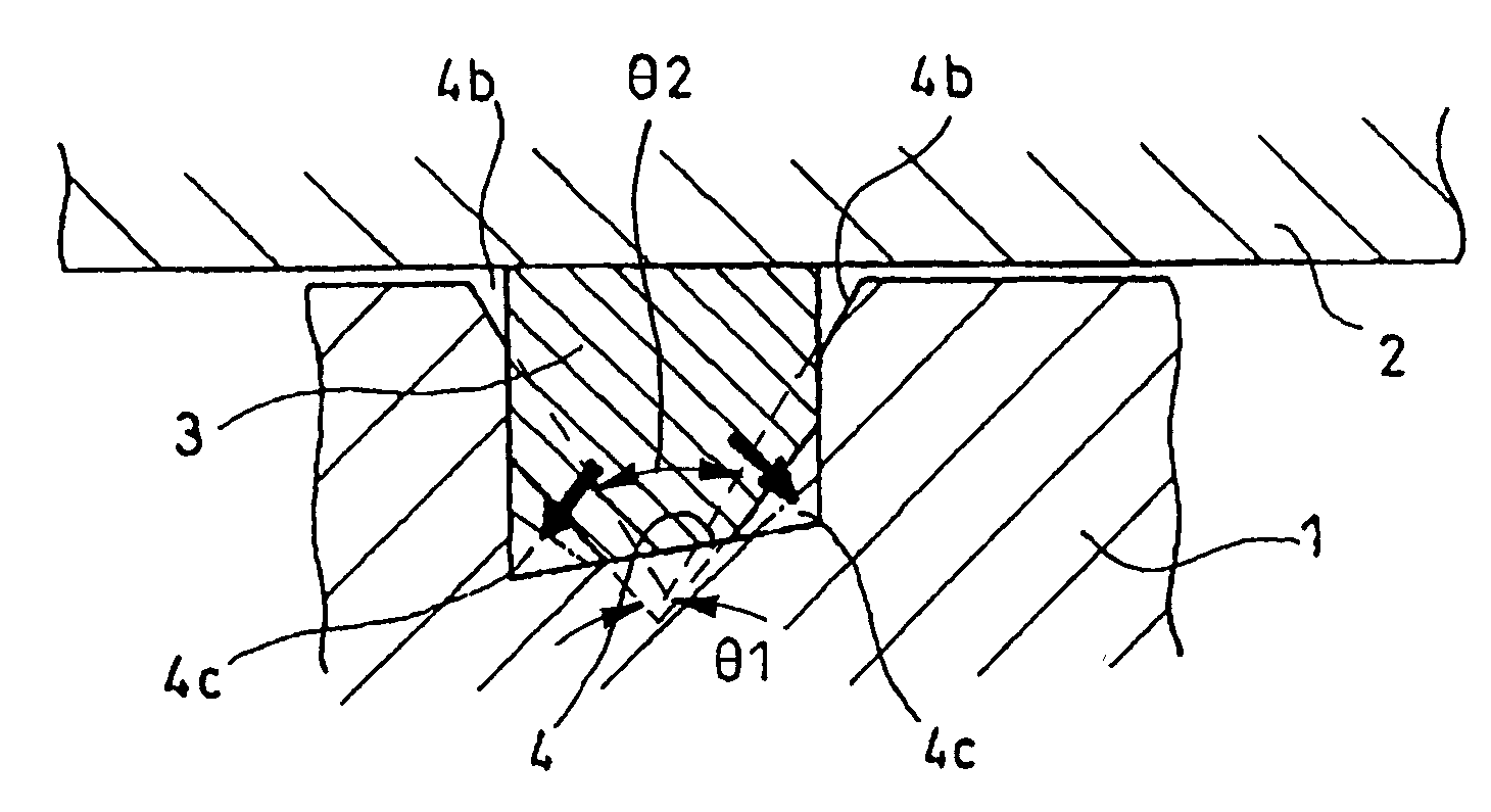
[0025]FIG. 1 is a sectional view showing the circumference of a piston seal 3 in the first embodiment of the invention. In this embodiment, each width (the dimension in a direction in which a brake piston 2 is slid) of the piston seal 3 and a seal groove 4 is substantially the same or the width of the seal groove 4 is set to a smaller value. As a result, the piston seal 3 is not expanded in an axial direction of the brake piston 2 and movement in the sliding direction is regulated. Therefore, the brake piston 2 is never pushed back and when the temperature rises. Thus, the characteristic (particularly, the quantity of play) of a brake can be stabilized.

[0026]Clearance between the seal groove 4 and the piston seal 3 is minimized adjacent to where the piston seal 3 is in contact with the brake piston 2. Instead, however, space 4b and space 4c are provided at the bottom of the seal groove 4 (away from where the piston seal 3 makes contact with the brake piston 2) by chamfering the oute...


PUM


Abstract

A disc brake includes a piston seal made of rubber that is shaped to fit into a seal groove on the inner surface of a cylinder of a caliper for a brake piston. To prevent braking effectiveness from being impaired, even if the temperature of a caliper rises in a disc brake for a vehicle, the piston seal and/or the seal groove is shaped to control and contain the effects of thermal expansion due to the heat of the disc brake. The clearance between the piston seal and the seal groove is removed and clearance is provided between parts of the periphery of the piston seal and the seal groove.

Description

CROSS-REFERENCE TO RELATED APPLICATIONS[0001]The present application claims priority under 35 USC 119 to Japanese Patent Application No. 2001-234059 filed on Aug. 1, 2001 the entire contents thereof is hereby incorporated by reference.BACKGROUND OF THE INVENTION[0002]1. Field of the Invention[0003]The present invention relates to a disc brake for a vehicle, such as an automobile or a motorcycle. More particularly, to piston seals and seal grooves for the disc brake.[0004]2. Description of the Background Art[0005]For this type of brake, a brake piston slides in and out of a caliper at the driver's command and places pressure on the disc brake to stop or slow the vehicle. For example, a disc brake is disclosed in Japanese published unexamined patent application No. Hei 9-72361.[0006]As shown in FIG. 10(a), a brake piston 02 is inserted into a cylinder 01 of a caliper for slideably mounting the brake piston. Located on the left side in FIG. 10(a), a pad and others are pressed upon a br...

Claims


Application Information

Patent Timeline
IPC IPC(8): F16D55/18F16J15/16F16D65/18
CPCF16J15/164F16D55/22
Inventor KURIMOTO, SEIJIWAKAMATSU, KUNIAKITOYODA, HIDETOSHIKUWAHARA, SHINICHI
Owner HONDA MOTOR CO LTD
Why Eureka
Try Eureka