
Remote controlled swing auger system

a remote control and swing auger technology, applied in mechanical conveyors, loading/unloading, packaging, etc., can solve the problems of heavy weight, difficult manual manipulation, and not being suitable for efficiently manipulating the position and achieve the effect of efficient manipulation of the swing auger position

Active Publication Date: 2007-03-20
RUST SALES
View PDF26 Cites 48 Cited by
  • Summary
  • Abstract
  • Description
  • Claims
  • Application Information

AI Technical Summary

Benefits of technology

[0010]In view of the foregoing disadvantages inherent in the known types of swing augers now present in the prior art, the present invention provides a new remote controlled swing auger system construction wherein the same can be utilized for efficiently manipulating a position of a swing auger.
[0016]A second object is to provide a remote controlled swing auger system for efficiently manipulating a position of a swing auger with respect to a semi hopper trailer or other trailer.
[0017]Another object is to provide a remote controlled swing auger system that does not require manual manipulation of a swing auger.
[0020]Another object is to provide a remote controlled swing auger system that efficiently unloads grain and other particulate material from a trailer.

Problems solved by technology

One of the main problems with conventional swing augers is that they are heavy and difficult to manually manipulate.
One of the problems with the hydraulically powered swing augers is that they require the tractor to be in operation to provide hydraulic pressure to the hydraulic motor.
Another problem with hydraulically powered swing augers is that they require the user to manipulate a valve near the swing auger requiring the user to leave the tractor to move the swing auger.
While these devices may be suitable for the particular purpose to which they address, they are not as suitable for efficiently manipulating a position of a swing auger.

Method used


Image

  • Remote controlled swing auger system
  • Remote controlled swing auger system
  • Remote controlled swing auger system

Examples


Embodiment Construction

A. Overview

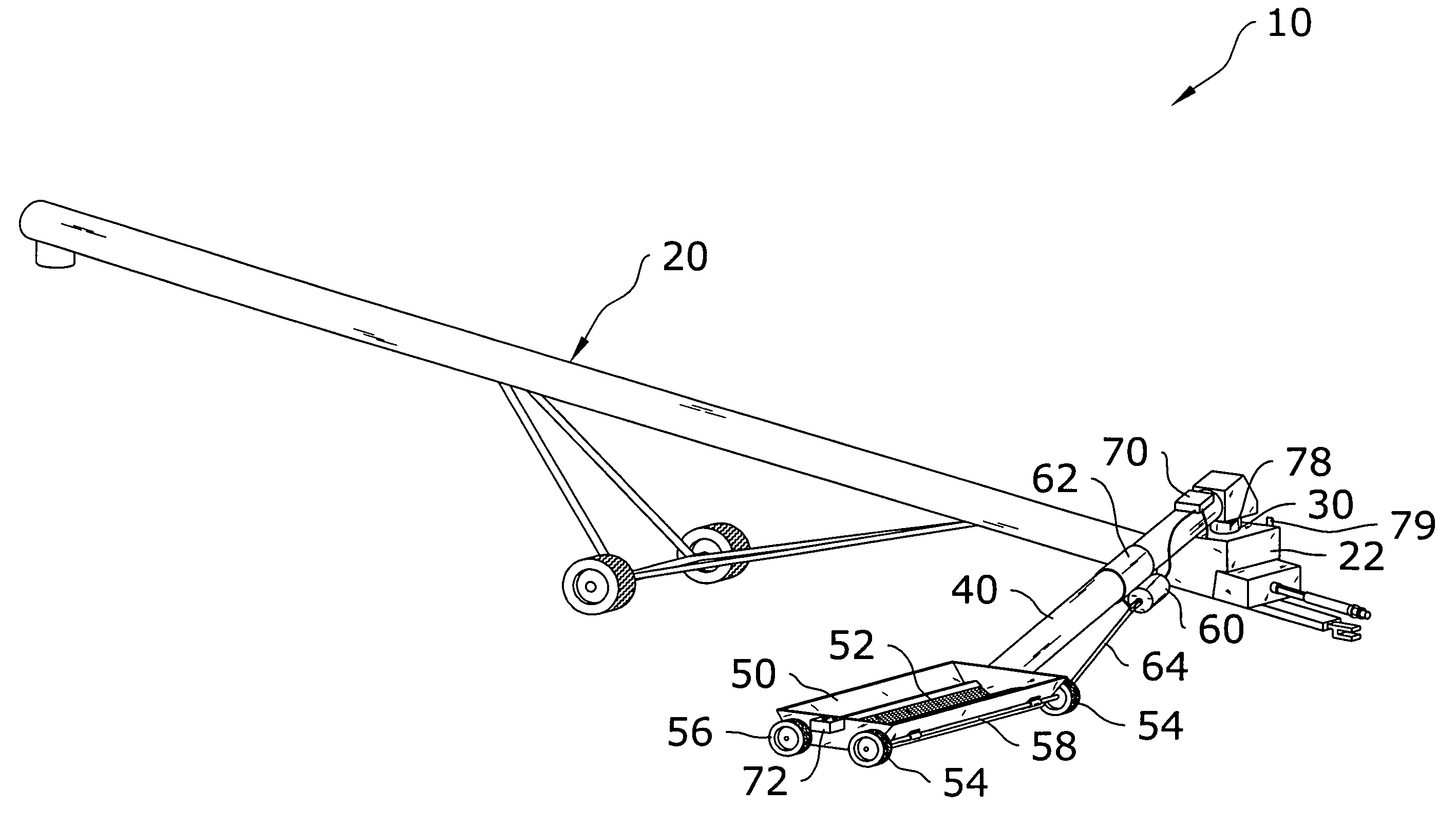
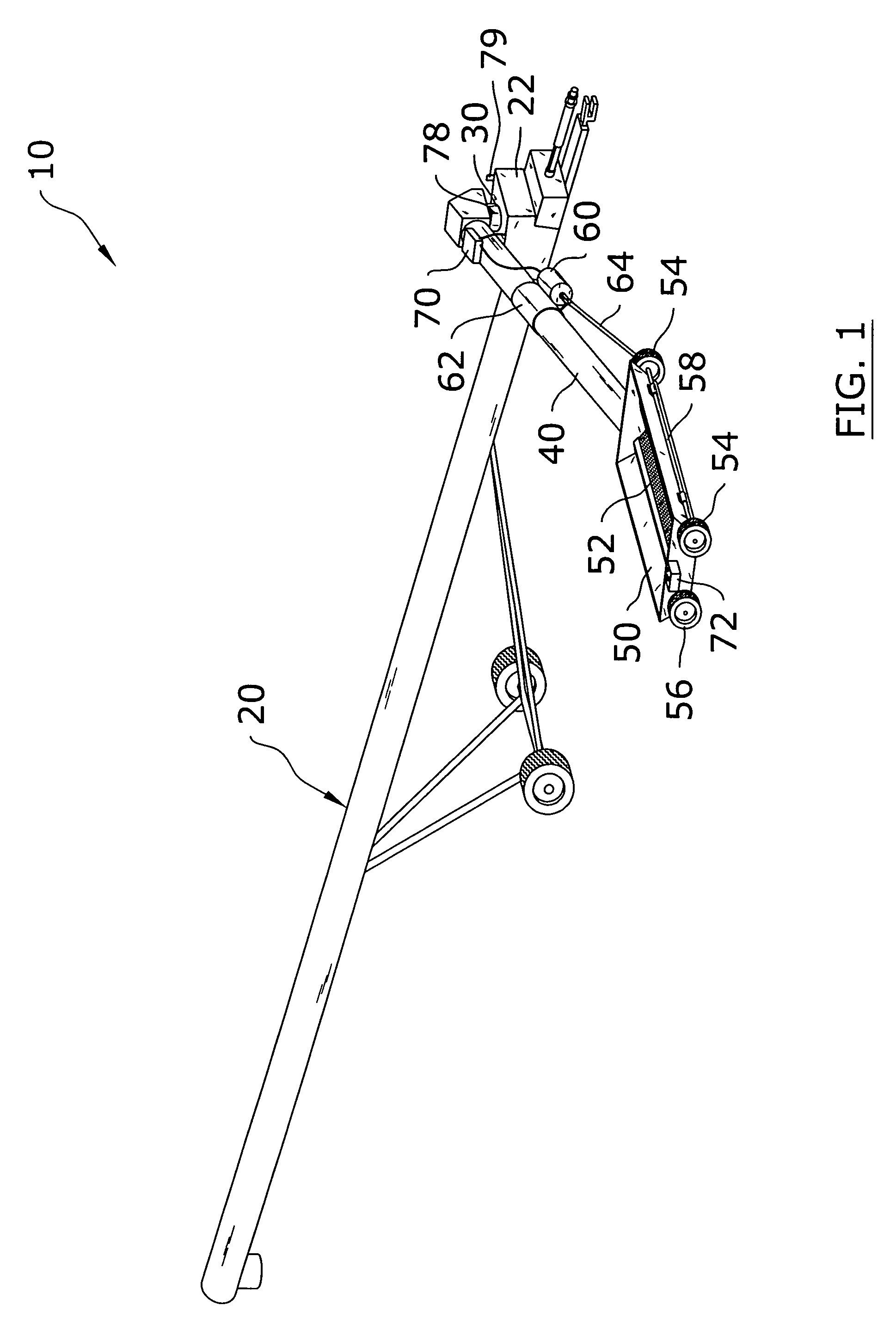
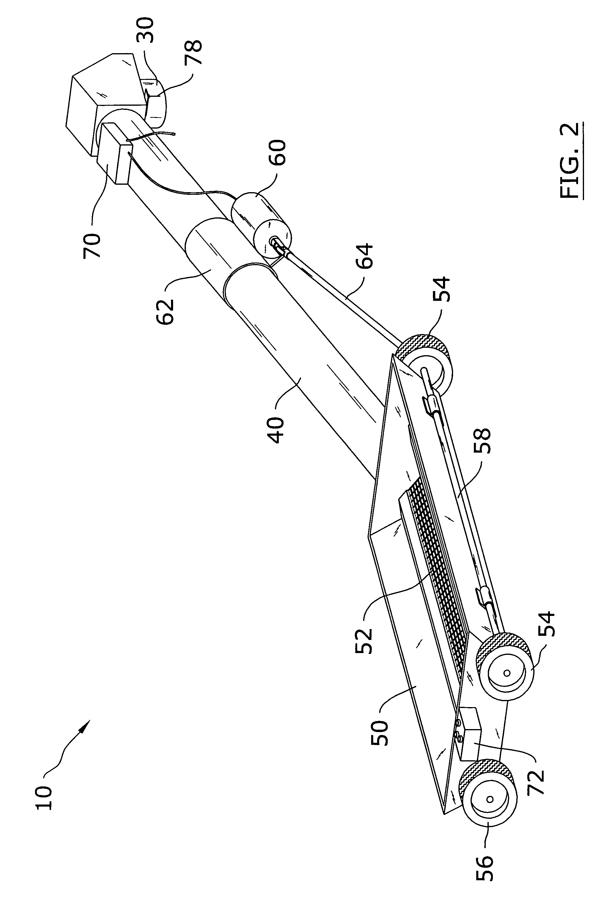
[0034]Turning now descriptively to the drawings, in which similar reference characters denote similar elements throughout the several views, FIGS. 1 through 10 illustrate a remote controlled swing auger system 10, which comprises a swing auger 40 connectable to a main auger 20, a swing hopper 50 connected to the swing auger 40, a plurality of front wheels 54 and a plurality of rear wheels 56 rotatably attached to the swing hopper 50, a drive motor 60 mechanically connected to the front wheels 54, a control unit 70 in communication with the drive motor 60, and at least one controller in communication with the control unit 70. The controller may be comprised of a manual controller 72 and / or a remote controller 74. The user is able to pivot the swing hopper 50 with respect to a main auger 20 by using the remote controller 74 while in the tractor or in a remote location away from the augers.

B. Main Auger

[0035]FIGS. 1, 3, 5, 6 and 7 illustrate a conventional main auger 20. Var...


PUM


Abstract

A remote controlled swing auger system for efficiently manipulating a position of a swing auger. The remote controlled swing auger system includes a swing auger connectable to a main auger, a swing hopper connected to the swing auger, a plurality of front wheels and a plurality of rear wheels rotatably attached to the swing hopper, a drive motor mechanically connected to the front wheels, a control unit in communication with the drive motor, and at least one controller in communication with the control unit. The controller may be comprised of a manual controller and / or a remote controller. The user is able to pivot the swing hopper with respect to a main auger by using the remote controller while in the tractor or in a remote location away from the augers.

Description

CROSS REFERENCE TO RELATED APPLICATIONS[0001]Not applicable to this application.STATEMENT REGARDING FEDERALLY SPONSORED RESEARCH OR DEVELOPMENT[0002]Not applicable to this application.BACKGROUND OF THE INVENTION[0003]1. Field of the Invention[0004]The present invention relates generally to swing augers and more specifically it relates to a remote controlled swing auger system for efficiently manipulating a position of a swing auger.[0005]2. Description of the Related Art[0006]Swing augers have been in use for years. Conventional swing augers are attachable to main auger which is well known in the art. One of the main problems with conventional swing augers is that they are heavy and difficult to manually manipulate.[0007]Recently, hydraulically powered swing augers such as the MK POWER SWING manufactured by WESTFIELD in Rosenort, Manitoba utilize hydraulic power from the tractor to drive auxiliary wheels added to the swing auger. One of the problems with the hydraulically powered sw...

Claims


Application Information

Patent Timeline
IPC IPC(8): B65G21/10
CPCB65G21/10B65G47/18B65G41/002B65G33/32
Inventor HELEY, KENNETH J.
Owner RUST SALES
Learn More