Methods and devices for high throughput fluid delivery

a high-throughput, fluid-delivering technology, applied in the direction of diaphragms, electrolysis, ratio control, etc., can solve the problems of limiting throughput, laborious process that consumes significant amount of time, and impedes the search for lead compounds in the development of these new pharmacological agents

Inactive Publication Date: 2007-03-20
CAPLIPER LIFE SCI INC
View PDF85 Cites 68 Cited by
  • Summary
  • Abstract
  • Description
  • Claims
  • Application Information

AI Technical Summary

Benefits of technology

[0007]The present invention generally relates to microfluidic device manifold systems and to methods of delivering reagents to microfluidic device components using the manifold systems. The invention additionally provides methods of fabricating manifolds for microfluidic devices. One advantage of the invention includes decreasing assay preparation time since reagents are typically loaded only one time for distribution to selected ports rather than multiple times to each of those ports individually. This may also help to conserve reagents which are often limited in supply. The invention additionally simplifies instrument design and provides for more reliable results by reducing the number of pressure / vacuum and / or the number of electrode interfaces with a particular device.
[0008]In particular, the present invention provides a microfluidic device that includes a body structure having a microchannel network and a plurality of ports disposed in the body structure. At least one port is in fluid communication with a microchannel in the microchannel network. The device also includes a manifold having a manifold channel network and an aperture disposed in the manifold. The aperture is in fluid communication with a manifold channel in the manifold channel network. Additionally, the manifold is mated with the body structure such that the aperture or one or more manifold channels in the manifold channel network is in fluid communication with one or more of the plurality of ports. The microchannel network disposed in the body structure typically extends in a substantially planar dimension, while the manifold channel network disposed in the manifold includes channels extending both horizontally and vertically within the manifold. Optionally, the microchannel network and the manifold channel network extend in at least horizontal and vertical planes.
[0009]In preferred embodiments, the aperture is in fluid communication with two or more manifold channels in which at least two of the two or more manifold channels also fluidly communicate with a different port. The devices of the present invention also typically include an additional aperture or manifold channel in fluid communication with the aperture, with the at least one or another manifold channel network, or with the port, for venting air when the devices are loaded with reagents or filled with another fluidic material. The manifolds of the invention also optionally include a first alignment structure for aligning the body structure on the first surface of the manifold.
[0010]The invention also includes a controller / detector apparatus (e.g., an automated apparatus) configured to receive the microfluidic device. The controller / detector apparatus generally includes an optical and / or an electrochemical detection system and a material transport system. The detection system and the transport system are operably interfaced with the microfluidic device.
[0011]In one embodiment, the devices include two or more manifolds, in which each of the two or more manifolds interchangeably mates with the body structure for distributing a fluid to one or more of the plurality of ports in the body structure. In another embodiment, the invention provides two or more body structures, in which each of the two or more body structures interchangeably mates with the manifold for distributing a fluid to one or more of the plurality of ports in the body structure. These embodiments also typically include an automated controller / detector apparatus, similar to the apparatus mentioned above, but which additionally includes a body structure or manifold interchange system.
[0012]In certain embodiments of the present invention, the body structure and the manifold are integrated. For example, each of the body structure and the manifold generally separately include a first surface. The plurality of ports is optionally disposed in the first surface of the body structure. Additionally, the aperture or the one or more manifold channels in the manifold channel network are optionally disposed in the first surface of the manifold. Upon integration, the first surface of the manifold is typically mated to the first surface of the body structure such that the aperture or the one or more manifold channels in the manifold channel network are in fluid communication with the plurality of ports disposed in the body structure. The first surface of the body structure and the first surface of the manifold are typically planar. When the manifold and body structure are integrated, the first surface of the manifold is typically mated to the first surface of the body structure using, e.g., adhesion, heat lamination, bonding, welding, clamping, or the like.

Problems solved by technology

However, the search for lead compounds in the development of these new pharmacological agents is often impeded by the lack of sufficient throughput of many assays.
Sources which limit throughput include the time and labor requirements associated with preparing each screen.
As a result, fluid introduction into these devices, whether accomplished manually using, e.g., a pipettor, or automatically using, e.g., a robotic fluid handling device, is often a laborious process that consumes significant amounts of time.

Method used


Image

  • Methods and devices for high throughput fluid delivery
  • Methods and devices for high throughput fluid delivery
  • Methods and devices for high throughput fluid delivery

Examples


Embodiment Construction

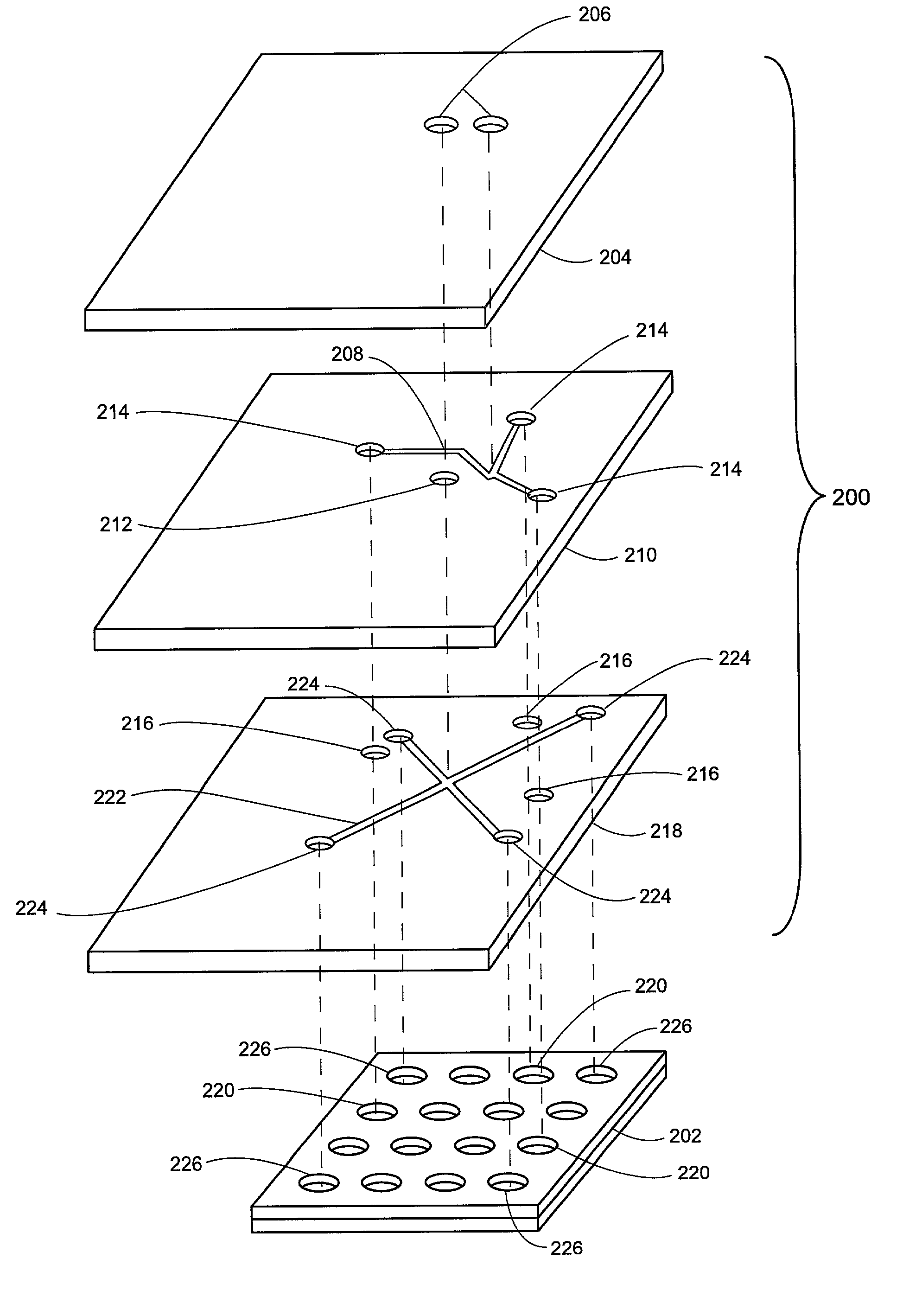
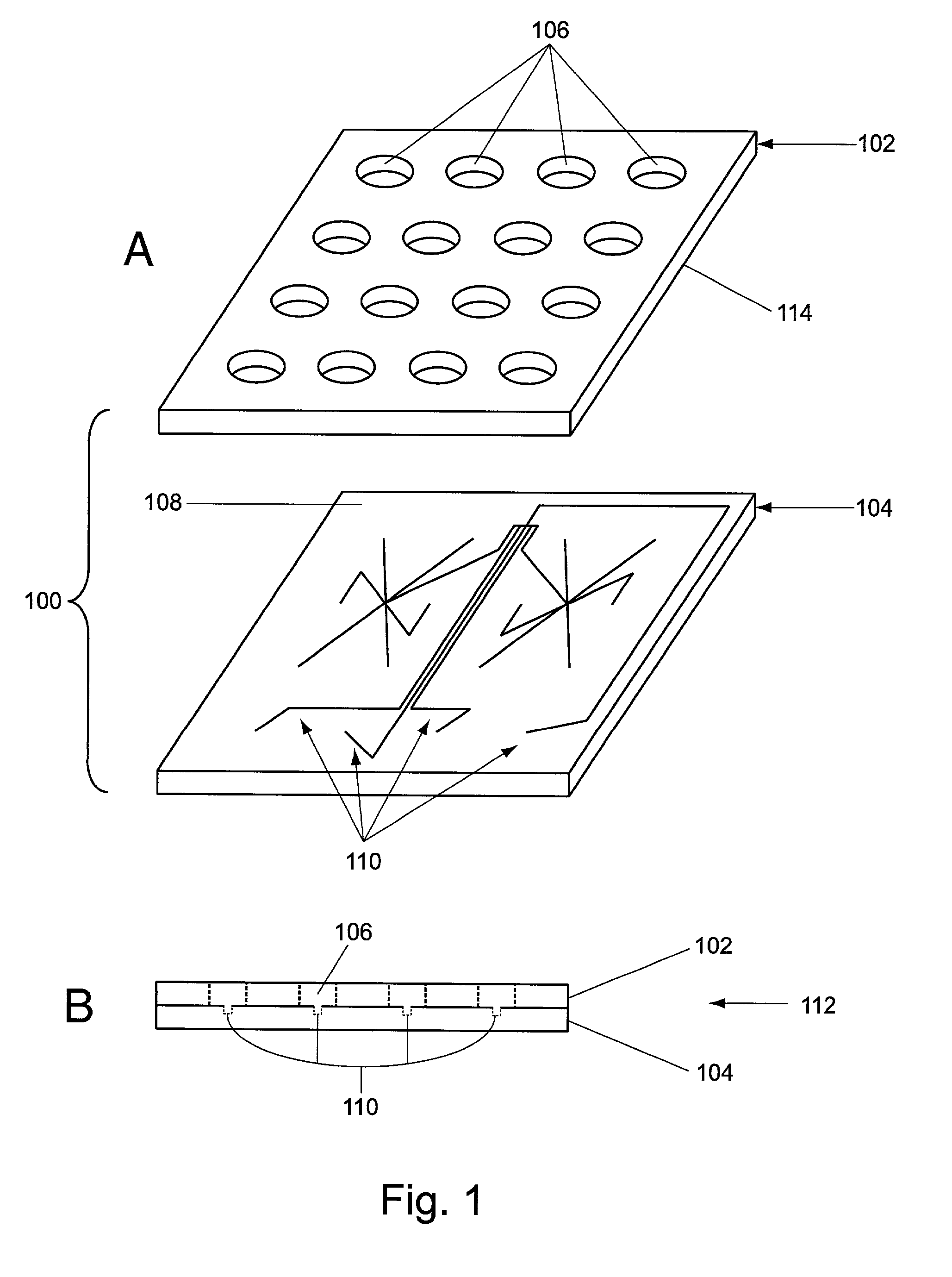
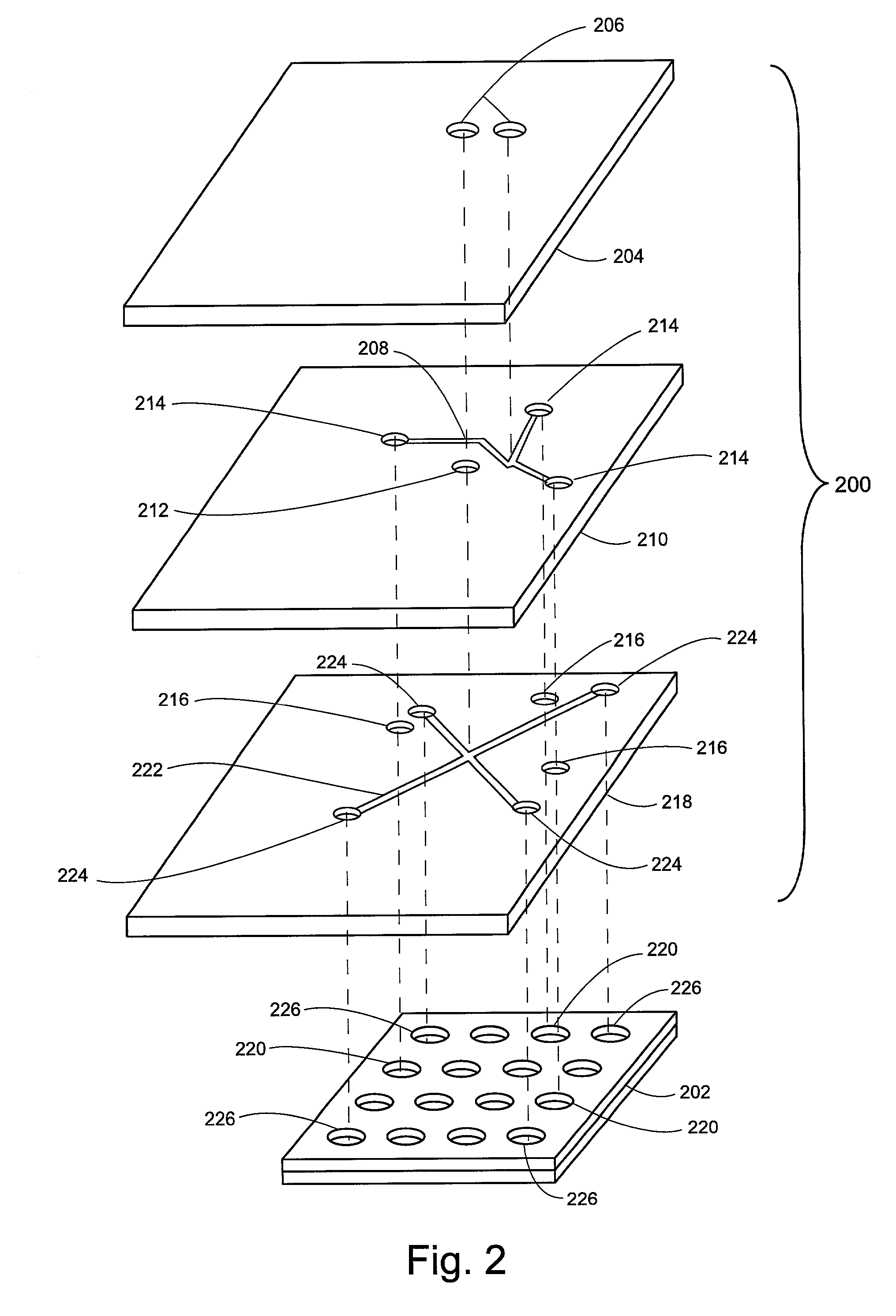
[0027]The present invention generally relates to fluid manifold systems and to improved methods of fluid delivery. In particular, the present invention is directed to manifold devices and to methods of utilizing those devices to deliver reagents or other fluid components to microfluidic device components. The invention also provides methods for fabricating manifolds for microfluidic devices.

[0028]In general, manifolds typically include three dimensional fluid distribution systems, such as apertures and / or manifold channel networks that interface external reagent reservoirs, wells, or ports disposed in surfaces of microfluidic device body structures. Body structures generally include at least one microchannel network that intersects with at least one port. Microchannel networks typically extend in a substantially planar dimension, which imposes certain topological constraints on fluid delivery. The manifolds of the present invention remove these constraints such that a single reagent...


PUM

PropertyMeasurementUnit
depthaaaaaaaaaa
depthaaaaaaaaaa
depthaaaaaaaaaa

Abstract

Methods and devices for delivering fluids into microfluidic device body structures are described. The methods and devices include the use of fluid manifolds which are integrated or interchangeable with device body structures. Methods of fabricating manifolds are also provided.

Description

CROSS-REFERENCES TO RELATED APPLICATIONS[0001]Pursuant to 35 U.S.C. §§ 119 and / or 120, and any other applicable statute or rule, this application claims the benefit of and priority to U.S. Ser. No. 60 / 222,884, filed on Aug. 3, 2000, the disclosure of which is incorporated by reference.COPYRIGHT NOTIFICATION[0002]Pursuant to 37 C.F.R. §1.71(e), Applicants note that a portion of this disclosure contains material which is subject to copyright protection. The copyright owner has no objection to the facsimile reproduction by anyone of the patent document or patent disclosure, as it appears in the Patent and Trademark Office patent file or records, but otherwise reserves all copyright rights whatsoever.BACKGROUND OF THE INVENTION[0003]Modern pharmaceutical discovery often involves assaying or screening immense collections of test compounds for their effects on specific target molecules. Combinatorial chemistry and associated technologies for generating molecular diversity have significant...

Claims


Application Information

Patent Timeline
Patent Type & Authority Patents(United States)
IPC IPC(8): B01L3/02B01L11/00B32B27/04B32B27/12B32B5/02B01D61/18B01L3/00B01L99/00B81B1/00
CPCB01D61/18B01L3/502707B01L3/502715B01L3/50273B01L3/5025Y10T436/11B01L3/502723B01L2200/027B01L2300/0861B01L2300/0867B01L2400/0406B01L2400/0415B01L2400/043B01L2400/0457Y10T436/2575Y10T137/2496Y10T137/2499Y10T137/2501Y10T137/2514Y10T137/2516
Inventor CHOW, ANDREA W.KOPF-SILL, ANNE R.PARCE, J. WALLACEDUBROW, ROBERT S.
Owner CAPLIPER LIFE SCI INC
Why Eureka
Try Eureka