High-intensity light emitting diode with concave and convex shaped light scattering portions formed on a cover

a light-emitting diode, high-intensity technology, applied in the direction of discharge tube luminescnet screen, discharge tube/lamp details, incadescent envelope/vessel, etc., can solve the problem of not being able to obtain sufficient light scattering effect, unfavorable light scattering effect, and inability to uniform light emission, so as to increase the scattering effect of light emitted, the effect of enlargement of the scattered range of light and equalization

Inactive Publication Date: 2007-03-20
CITIZEN ELECTRONICS CO LTD
View PDF16 Cites 20 Cited by
  • Summary
  • Abstract
  • Description
  • Claims
  • Application Information

AI Technical Summary

Benefits of technology

[0012]It is therefore a first object of the present invention to provide a light emitting diode capable of accomplishing enlargement of scattered range of

Problems solved by technology

Consequently, it is not possible to obtain a large scattering effect of light.
As a result, there is a problem that the light emission is not uniform in accordance with an angle of viewing the light emitting projected surface.
Inversely, if the amount of mixing the particles 7 is less, it i

Method used


Image

  • High-intensity light emitting diode with concave and convex shaped light scattering portions formed on a cover
  • High-intensity light emitting diode with concave and convex shaped light scattering portions formed on a cover
  • High-intensity light emitting diode with concave and convex shaped light scattering portions formed on a cover

Examples


Embodiment Construction

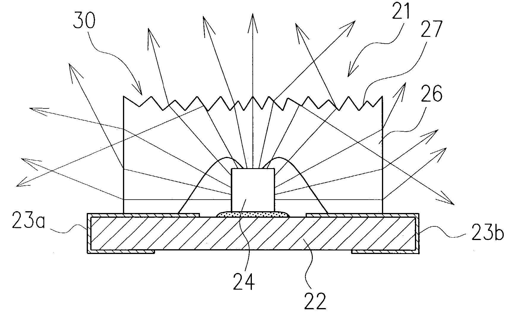
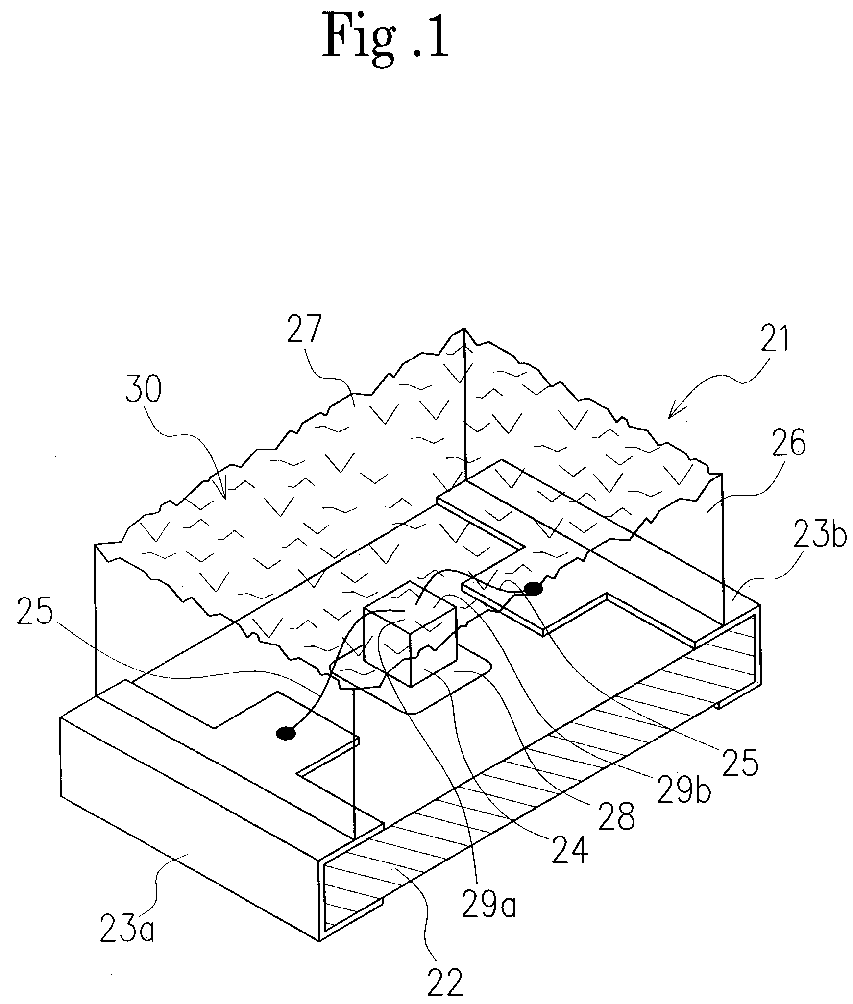
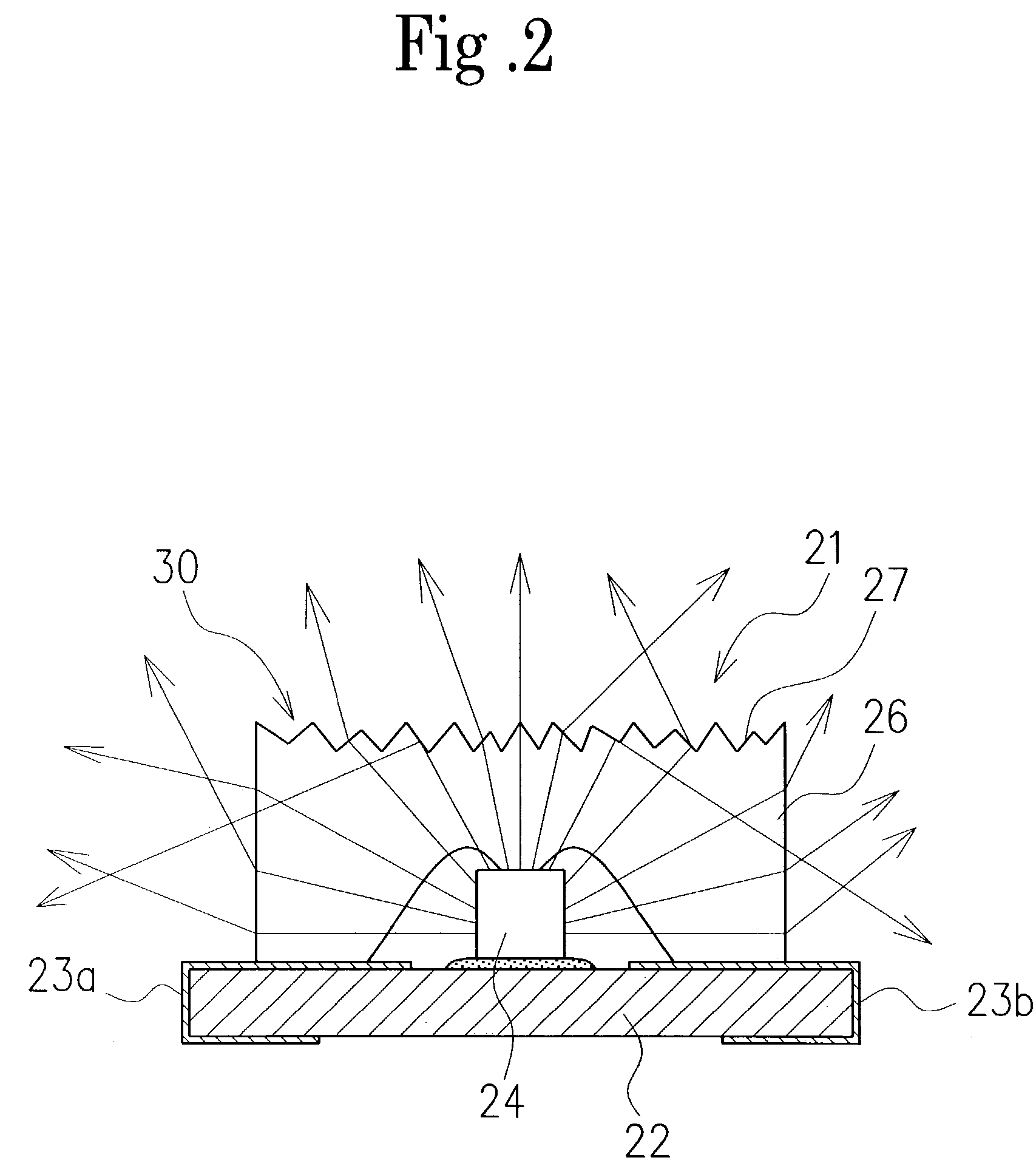
[0032]Referring to FIG. 1, one embodiment of a light emitting diode according to the present invention is shown.

[0033]The light emitting diode 21 in the embodiment comprises a substrate 22 made of glass epoxy, BT resin (bismaleimide triazine resin) or the like, a pair of electrodes 23a and 23b mounted on the substrate 22, a light emitting element 24 mounted on the substrate 22, bonding wires 25 for connecting electrically the light emitting element 24 and electrodes 23a and 23b, and a cover 26 for sealing the light emitting element 24, electrodes 23a and 23b and at least connecting portions between the electrodes and bonding wires.

[0034]In this way, covering the light emitting element 24, electrodes 23a and 23b, bonding wires 25 and so on by the cover 26 causes the portions covered by the cover to be protected from corrosion.

[0035]Note that the electrodes 23a and 23b may be mounted on an outside substrate of a mother board (not shown) and so on.

[0036]The light emitting element 24 ma...


PUM


Abstract

A light emitting diode, capable of accomplishing enlargement of emitted range of light and equalization of brightness of emitted light has a substrate (22), electrodes (23a, 23b), a light emitting element (24) mounted on the substrate (22) and connected electrically with the electrodes (23a, 23b), a resinous cover (26) for sealing the light emitting element (24) and electrodes (23a, 23b) and an uneven shaped light scattering part (30) provided on the surface of the cover.

Description

BACKGROUND OF THE INVENTION[0001]1. Field of the Invention[0002]The present invention relates to a light emitting diode, more specifically, to a light emitting diode capable of scattering widely and efficiently emitted light.[0003]2. Description of the Prior Art[0004]Generally, a light emitting diode for emitting light by a current is well known.[0005]A conventional typical light emitting diode 1 is shown in FIG. 5. The light emitting diode 1 comprises a substrate 2, a pair of electrodes 3a and 3b mounted on the substrate 2, a light emitting element 4 fixed on the substrate 2, bonding wires 5 for connecting the light emitting element 4 with the electrodes 3a and 3b and a resinous cover 6 mounted on the substrate to seal the light emitting element 4 and bonding wires 5.[0006]The cover 6 acts to prevent the light emitting element 4 and bonding wires 5 from corroding and so on, and is formed from a transparent epoxy resin material to pass through light emitted from the light emitting e...

Claims


Application Information

Patent Timeline
IPC IPC(8): H01L33/00H01J1/62H01L33/22H01L33/54H01L33/56
CPCH01L33/44H01L33/54H01L2224/32245H01L2224/48091H01L2224/48227H01L2224/73265H01L2924/12041H01L2933/0091H01L2924/10253H01L2224/32225H01L2924/1815H01L2924/00014H01L2924/00
Inventor ISHIZAKA, MITSUNORI
Owner CITIZEN ELECTRONICS CO LTD
Why Eureka
Try Eureka